

doi: 10.1109/TCSI.2010.2089556.
Silicon-Neuron Design: A Dynamical Systems Approach
Affiliations
- PMID: 21617741
- PMCID: PMC3100558
- DOI: 10.1109/TCSI.2010.2089556
Item in Clipboard
Silicon-Neuron Design: A Dynamical Systems Approach
IEEE Trans Circuits Syst I Regul Pap.
2011.
Abstract
We present an approach to design spiking silicon neurons based on dynamical systems theory. Dynamical systems theory aids in choosing the appropriate level of abstraction, prescribing a neuron model with the desired dynamics while maintaining simplicity. Further, we provide a procedure to transform the prescribed equations into subthreshold current-mode circuits. We present a circuit design example, a positive-feedback integrate-and-fire neuron, fabricated in 0.25 μm CMOS. We analyze and characterize the circuit, and demonstrate that it can be configured to exhibit desired behaviors, including spike-frequency adaptation and two forms of bursting.
Figures

Measured silicon neuron membrane traces (x, normalized) rise like a resistor-capacitor circuit, with a positive feedback spike for several step-input current levels (r=0.48, 0.57, 0.69, 0.82, 0.98, and 1.2). Below a threshold input, the neuron reaches a steady state at which the input and positive feedback are insufficient to overpower the leak. Above threshold, larger inputs enable the positive feedback to overcome the leak more quickly, resulting in a shorter time to spike. Inset The neuron’s phase plot shows ẋ versus x (black), fit with a cubic (gray). The neuron has two fixed points (circles) when its input is small, r < 2/3, one stable (filled) and one unstable (open). As r increases above 2/3, the fixed points merge and destroy each other, undergoing a saddle-node bifurcation, the transition from resting to spiking. Phase plot traces filtered by a 5 ms halfwidth gaussian.

The neuron circuit comprises a capacitor Cx, driven by three currents: an input (Mr), a leak (ML), and positive feedback (MF1–5). When the input and positive feedback currents drive Vx low enough, REQ transitions from low to high, signaling a spike.

The silicon neuron responds sublinearly to current above a threshold (dots). See text for fit equation. Inset f2 is fit (gray line) versus the input to find and normalize to the threshold r = 2/3.

The neuron expresses frequency bistability when reset to 1.7. Initially, when the input is low, r = 0.36, the neuron is silent, but when it increases to 0.70 then, drops back to 0.36, the neuron spikes at 22 Hz. Inset The neuron trajectory (black) follows the fits for r = 0.36, 0.70 (gray). When it is reset above the unstable point (open circle) for r = 0.36, the neuron spikes; otherwise it sits at the stable point (filled circle). Phase plot traces filtered by a 5 ms halfwidth gaussian.

In square-wave bursting, as gk decays the burst begins, x spikes rapidly until gk overcomes the positive feedback. Inset The neuron rests at its stable point (closed circle), which becomes destabilized when the ẋ versus x curve rises as gk decays, starting a burst (arrows). During the burst, the ẋ versus x curve drops as gk rises, eventually pushing the unstable point (open circle) above xres, which terminates the burst. Phase plot and gk traces filtered by a 5 ms halfwidth gaussian.

The ion-channel population circuit consists of two modules, one implements the pulse-like spike response, p(t) (Mp1,2 and Cp), and the other implements the first-order dynamics, Vch (Mch1–3 and Cch). Vch generates the output current, Ich, when it is applied to the gate of an output transistor Mout.

To implement adapting and bursting the neuron circuit is augmented with two ion-channel population circuits, realizing gk (Mk) and rca (Mca), and a reset circuit (Mres).

In square-wave bursting, x and gk follow a trajectory (black) in which x moves towards either a stable equilibrium or a spiking limit cycle. Initially for low gk (below 0.22), x enters the spiking limit cycle (light gray shading). As gk increases (between 0.22 and 1.22), x remains in its spiking limit cycle, even though a stable point and an unstable point have appeared (solid and dashed lines). Once gk exceeds 1.22, the limit cycle becomes unstable (dark gray shading); x drops to its only stable point, until gk decays below 0.22, repeating the cycle. Traces filtered by a 5 ms halfwidth gaussian; dots are 5 ms apart.

In spike-frequency adaptation, as gk (dark gray) increases x’s (light gray) spike frequency decreases. Inset gk decreases frequency by decreasing ẋ (black) towards zero, slowing spiking. Fits (gray) are a guide for the eye. Phase plot and gk traces filtered by 10 and 5 ms halfwidth gaussians, respectively.

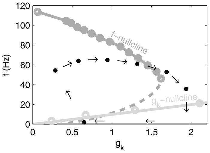
In spike-frequency adaptation, f starts high but decreases as gk increases (arrows), following the f-nullcline (light gray) until it crosses the gk nullcline, reaching a stable equilibrium. Each dot corresponds to one interspike interval’s instantaneous f and mean gk. gk values filtered by a 5 ms halfwidth gaussian.

In parabolic bursting, as gk (dark gray) decays the burst begins, x (light) spikes faster then slower until the burst ends. Inset gk shifts the conceptual f(rca) curve. For medium gk (middle curve), two stable points coexist (filled circles), one at a high frequency and one at a low, with an unstable point in between (open circle). For low gk (top curve), the low stable point collides with the unstable point, leaving only the high stable point, initiating spiking. For high gk (bottom curve), the high stable point collides with the unstable point, leaving only the low stable point, terminating spiking. gk filtered by a 5 ms halfwidth gaussian.
In parabolic bursting, f and gk follow a trajectory (black) in which both move towards stable portions of their respective nullclines (dark and light gray). Each dot corresponds to one interspike interval’s instantaneous f and mean gk. gk values filtered by a 5 ms halfwidth gaussian.
References
-
- Mead CA. Analog VLSI and Neural Systems. Reading, MA: Addison-Wesley; 1989.
-
- Indiveri G, Chicca E, Douglas R. A VLSI array of low-power spiking neurons and bistable synapses with spike-timing dependent plasticity. IEEE Transactions on Neural Networks. 2006;17(1):211–221. - PubMed
-
- Folowosele F, Harrison A, et al. A switched capacitor implementation of the generalized linear integrate-and-fire neuron. International Symposium on Circuits and Systems, ISCAS’09; IEEE Press; 2009. pp. 24–27.
-
- Mahowald M, Douglas R. A silicon neuron. Nature. 1991;354:515–518. - PubMed
-
- Simoni MF, Cymbalyuk GS, Sorensen ME, Calabrese RL, DeWeerth SP. A multiconductance silicon neuron with biologically matched dynamics. IEEE Transactions on Biomedical Engineering. 2004;51(2):342–354. - PubMed
Grants and funding
LinkOut - more resources
Full Text Sources
Other Literature Sources