. 2011;12(5):3263-87.
doi: 10.3390/ijms12053263. Epub 2011 May 18.

Microfluidic mixing: a review

Affiliations

Microfluidic mixing: a review

Chia-Yen Lee et al. Int J Mol Sci. 2011.

Abstract

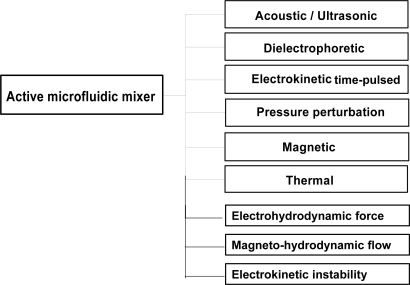
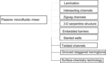
The aim of microfluidic mixing is to achieve a thorough and rapid mixing of multiple samples in microscale devices. In such devices, sample mixing is essentially achieved by enhancing the diffusion effect between the different species flows. Broadly speaking, microfluidic mixing schemes can be categorized as either "active", where an external energy force is applied to perturb the sample species, or "passive", where the contact area and contact time of the species samples are increased through specially-designed microchannel configurations. Many mixers have been proposed to facilitate this task over the past 10 years. Accordingly, this paper commences by providing a high level overview of the field of microfluidic mixing devices before describing some of the more significant proposals for active and passive mixers.

Keywords: active mixer; microfluidic mixing; passive micromixer.


Figures

Figure 1.
Figure 1.
Categories of active microfluidic mixer.
Figure 2.
Figure 2.
Schematic showing a number of air pockets in the top layer of the DNA biochip chamber: (a) overview; and (b) side view [26].
Figure 3.
Figure 3.
(a) Microphotograph of the DEP micromixer and (b) Schematic representation of circulating transverse flows (rolls) generated by AC electroosmosis which superimpose to the axial pressure driven flow within the micromixer. The positions of the asymmetric vortexes are twisted along the channel length in such a way as to implement a linked-twisted-map [3].
Figure 3.
Figure 3.
(a) Microphotograph of the DEP micromixer and (b) Schematic representation of circulating transverse flows (rolls) generated by AC electroosmosis which superimpose to the axial pressure driven flow within the micromixer. The positions of the asymmetric vortexes are twisted along the channel length in such a way as to implement a linked-twisted-map [3].
Figure 4.
Figure 4.
Sequence of concentration distribution in confluent stream mixing [33].
Figure 5.
Figure 5.
Model of a chaotic mixer with multiple side channels. (a) Experimental results of mixing in the device with one pair of side channels. The pressure perturbations induce lobe-like distortions of the interface and facilitate rapid mixing; (b) Schematic showing the new mixer with multiple side channels [40].
Figure 6.
Figure 6.
Schematic of the microfluidic system that includes a nozzle-diffuser-based bubble pump, a meander-shape fluid mixing channel and a gas bubble filter [42].
Figure 7.
Figure 7.
Schematic diagram of: (a) magnetic micromixer; (b) time-dependent current applied to the electromagnets and (c) mixing microchannel [9].
Figure 8.
Figure 8.
Microscopic images of microfludic mixer with parallelogram barriers in mixing channel [48].
Figure 9.
Figure 9.
Categories of passive microfluidic mixer.
Figure 10.
Figure 10.
Schematic diagram of micro T-mixer [60].
Figure 11.
Figure 11.
Simulated flow field in one mixing module showing lamination [14].
Figure 12.
Figure 12.
Photomicrograph of picoliter-volume mixer [62].
Figure 13.
Figure 13.
Top view of micromixer as two samples enter the first main channel segment [63].
Figure 14.
Figure 14.
Dimensions of the microfluidic system integrating a “Y” junction with channel width w, linear length of the periodic step s, and linear length of the zigzag microchannel L [64].
Figure 15.
Figure 15.
(A) Schematic diagram of channel with ridges; (B) Optical micrograph showing a top view of a red stream and a green stream flowing on either side of a clear stream in the channel and (C) Fluorescent confocal micrographs of vertical cross sections of the microchannel [66].
Figure 16.
Figure 16.
Geometry of: (a) three-dimensional serpentine and (b) stagger herringbone mixers [68].
Figure 17.
Figure 17.
Composite microscope image of fluorescence intensity and profiles of measured concentration at selected element outlets (k) derived from the images [16].
Figure 18.
Figure 18.
Schematic diagrams of barrier embedded Kenics micromixer [72].
Figure 19.
Figure 19.
(a) Top-view schematic of the simulation geometry for T-channel; (b) End-view schematic of the simulation geometry as viewed down the line of sight of (a) along with arrows depicting the general direction of the electric field within the slanted wells. Ex, Ey, and Ez are the components of the electric field and d is the depth of the channel [75].
Figure 20.
Figure 20.
(a) Schematic diagrams (upside down) of (a) T-mixer; (b) inclined mixer; (c) oblique mixer and (d) wavelike mixer [77].
Figure 21.
Figure 21.
Schematic illustration of electrical double layer (EDL) and electroosmotic flow near the EDL: (a) the EDL next to a negatively charged solid surface (ψ is the EDL potential, ψ0 is the surface electric potential, ζ is the zeta potential); (b) a homogeneous surface (ζ = −ζ0) and (c) a homogeneous surface with a heterogeneous region (ζ = +ζ0), ζ0 > 0 [82].

References

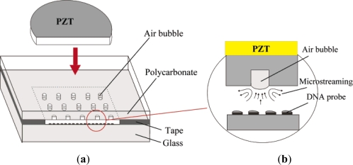
    1. Ahmed D, Mao X, Juluri B, Huang T. A fast microfluidic mixer based on acoustically driven sidewall-trapped microbubbles. Microfluid. Nanofluid. 2009;7:727–731.
    1. Luong T, Phan V, Nguyen N. High-throughput micromixers based on acoustic streaming induced by surface acoustic wave. Microfluid. Nanofluid. 2011;10:619–625.
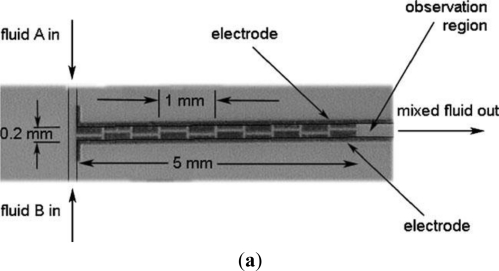
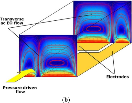
    1. Campisi M, Accoto D, Damiani F, Dario P. A soft-lithographed chaotic electrokinetic micromixer for efficient chemical reactions in lab-on-chips. J. Micro-Nano Mech. 2009;5:69–76.
    1. Chen CK, Cho CC. Electrokinetically driven flow mixing utilizing chaotic electric fields. Microfluid. Nanofluid. 2008;5:785–793.
    1. Lim C, Lam Y, Yang C. Mixing enhancement in microfluidic channel with a constriction under periodic electro-osmotic flow. Biomicrofluidics. 2010;4:014101. - PMC - PubMed

LinkOut - more resources