

Perception of 3-D Layout in Stereo Displays
Affiliations
- PMID: 21687822
- PMCID: PMC3115721
Item in Clipboard
Perception of 3-D Layout in Stereo Displays
Inf Disp (1975).
2009 Jan.
Abstract
As stereoscopic displays become more commonplace, it is more important than ever for those displays to create a faithful impression of the 3-D structure of the object or scene being portrayed. This article reviews current research on the ability of a viewer to perceive the 3-D layout specified by a stereo display.
Figures
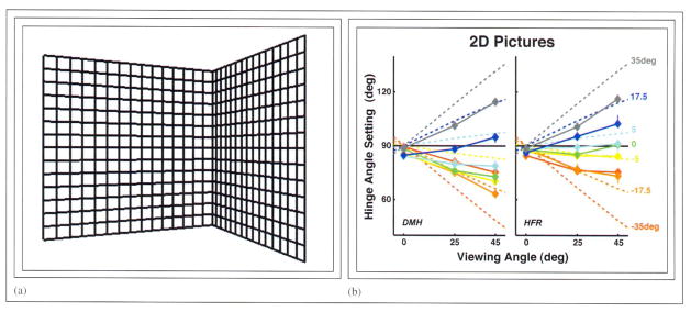
Hinge stimulus, predictions, and results for the experiment with conventional pictures. (a) An example of the hinge stimulus. The stimulus was presented on a conventional flat-screen display and viewed binocularly. Viewing angle (the angle between a line from the hinge to the center of projection and a line from the hinge to the viewer) was varied by rotating the display about a vertical axis. (b) Predictions and results. The hinge angle in the depicted stimulus that was on average perceived as 90° is plotted as a function of viewing angle. The left and right panels show data from subjects DMH and HRF, respectively. The compensation prediction is represented by the horizontal black lines at 90°. The no-compensation predictions are represented by the dashed colored lines, each line representing a different base slant. The symbols represent the data, the colors corresponding to different base slants. Error bars represent 95% confidence intervals.

Predicted 3-D percepts for the hinge stimulus for different viewing situations. Each panel shows an overhead view of the observer (gray), stereo cameras (blue), display surface (yellow), original stimulus (gray), and the predicted perceived stimulus (blue). The parameters used in the simulation are the following. Acquisition (camera) parameters: Parallel orientation of optical axes, inter-camera separation of 6.2 cm, focal length of 6.5 mm. Display parameters: one display device, picture magnification (projected size divided by film size) of 69.2. Viewing parameters: viewing distance of 45 cm, inter-ocular distance of 6.2 cm, viewer positioned such that midpoint of inter-ocular axis is on central surface normal of display device, viewer oriented with face parallel to display surface, stimulus is a 30 × 30-cm vertical hinge with a hinge angle of 90°. (c) With all parameters correctly set, the original and predicted perceived stimuli are identical. (a) The viewer is too close to the display. The predicted perceived hinge angle is greater than 90°. (e) Viewer is too far from the display. The perceived angle is now less than 90°. (b) Viewer is translated to the left of the display. The predicted hinge rotates toward the viewer and the predicted angle is less than 90°. (d) Viewer is translated to the right of the display. The predicted hinge rotates toward the viewer and the predicted angle is less than 90°.
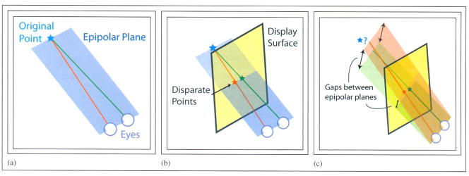
Epipolar geometry. (a) In the natural environment, an epipolar plane is defined by a point in visible space and the centers of the two eyes, (b) If the acquisition, display, and viewing parameters are correctly set, the epipolar planes produced by two corresponding points in the left- and right-eye pictures will coincide and the rays projected from the eyes through those points will intersect in space. (c) If the viewer’s head is rotated about a vertical axis (yaw rotation), the corresponding points in the left- and right-eye pictures produce rays that generally do not intersect because they lie in different epipolar planes.

Hinge stimulus, predictions, and results for the experiment with stereo pictures, (a) An example of the hinge stimulus. Cross-fuse the stimulus (direct the right eye to the left image and the left eye to the right image) to see it stereoscopically. Separate stimulation of the two eyes was accomplished by using liquid-crystal shutter glasses that were synchronized to the computer display. Viewing angle was varied by rotating the display about a vertical axis. (b) Predictions and results. The hinge angle in the depicted stimulus that was on average perceived as 90° is plotted as a function of viewing angle. The left and right panels show data from subjects DMH and RTH, respectively. The compensation prediction is represented by the horizontal black lines at 90°. The no-compensation predictions are represented by the dashed colored lines, each line representing a different base slant. Because the viewer was translated and rotated from the correct viewing position, epipolar geometry was not strictly followed. We made the predictions based on the disparities at the horizontal meridians of the eyes where rays from the eyes do intersect in space. The symbols represent the data, the colors correspond to different base slants. Error bars represent standard errors.
References
-
- Kubovy M. The Psychology of Perspective and Renaissance Art. Cambridge University Press; Cambridge. U.K: 1986.
-
- Woods AJ, Docherty T, Koch R. Image distortions in stereoscopic video systems. In: Merritt JO, Fisher SS, editors. Proc SPIE: Stereoscopic Displays and Applications IV. 1993. pp. 36–47.
-
- Shapiro LG, Stockman GC. Computer Vision. Prentice Hall; 2001.
Grants and funding
LinkOut - more resources
Full Text Sources
Research Materials