. 2011 Jul 12;108(28):11350-5.
doi: 10.1073/pnas.1107917108. Epub 2011 Jun 21.

Measurement of c-axis angular orientation in calcite (CaCO3) nanocrystals using X-ray absorption spectroscopy

Affiliations

Measurement of c-axis angular orientation in calcite (CaCO3) nanocrystals using X-ray absorption spectroscopy

P U P A Gilbert et al. Proc Natl Acad Sci U S A. .

Abstract

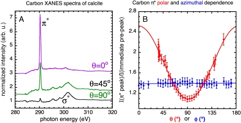
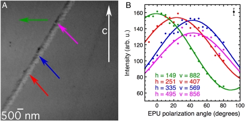
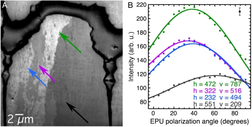
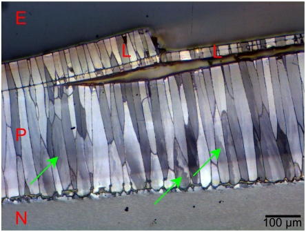
We demonstrate that the ability to manipulate the polarization of synchrotron radiation can be exploited to enhance the capabilities of X-ray absorption near-edge structure (XANES) spectroscopy, to include linear dichroism effects. By acquiring spectra at the same photon energies but different polarizations, and using a photoelectron emission spectromicroscope (PEEM), one can quantitatively determine the angular orientation of micro- and nanocrystals with a spatial resolution down to 10 nm. XANES-PEEM instruments are already present at most synchrotrons, hence these methods are readily available. The methods are demonstrated here on geologic calcite (CaCO(3)) and used to investigate the prismatic layer of a mollusk shell, Pinctada fucata. These XANES-PEEM data reveal multiply oriented nanocrystals within calcite prisms, previously thought to be monocrystalline. The subdivision into multiply oriented nanocrystals, spread by more than 50°, may explain the excellent mechanical properties of the prismatic layer, known for decades but never explained.


Conflict of interest statement

The authors declare no conflict of interest.

Figures

Fig. 1.
Fig. 1.
(A) XANES spectra of the carbon K edge obtained from a single crystal of calcite, at three linear polarization vector angles. We define the polar angle θ to be the angle between the calcite c axis and the linear polarization vector. Fig. S1 gives a complete description of the calcite crystal and its c-axis direction. The π and σ peak intensities are anticorrelated: At large polar angles (θ = 90°) the π and σ peaks have minimum and maximum intensity, respectively. The π peak is most intense at low polar angles (θ = 0°). This effect, known as X-ray linear dichroism, is the basis for PIC mapping. (B) Polar dependence (red data points) is obtained by plotting the intensity of the π peak at 290.3 eV as a function of the polar angle θ. In this case, the linear polarization vector was fixed while the calcite crystal was rotated. As expected and predicted by theory (9), the peak intensities vary as cos2θ (the red curve is a fit of the π peak intensity to the form A + B cos2θ). The azimuthal angle ϕ is the rotation angle of the ab plane of the crystal about the c axis. The azimuthal dependence (blue data points) was obtained by varying ϕ, while keeping θ constant at 64°. No variation in the π peak intensity is observed as a function of ϕ, at this or any other angle.
Fig. 2.
Fig. 2.
Stack of X-PEEM images of a geologic calcite crystal with a line of calcite defects, acquired while varying the angle of the linear polarization vector with respect to the vertical in the EPU (here referred to as EPU polarization angle or EPU°). The main crystal imaged here is illuminated by X-rays from the right-hand side of this image, as shown in the schematic of Fig. 3, and has its c axis oriented vertically, and in the plane of the sample surface. Each image in the stack is composed of 106 pixels, and the field of view is 10 μm. The stack of images of the same field of view was acquired at 19 polarization angles, varying from horizontal (EPU° = 90°) to vertical (EPU° = 0°) every 5°. An animated version of this stack is shown in Movie S1. (A) Average of all 19 images. The vertical white arrow indicates the direction of the c axis of the main geologic calcite crystal, as determined using X-ray diffraction. The lighter gray level line across the field of view is a defect that contains randomly oriented nanocrystals of calcite. The colored arrows indicate the positions of the single pixels from which the polar spectra in B were acquired. (B) Intensity of the π peak at a photon energy of 290.3 eV versus EPU polarization angle. These spectra were extracted from the 10-nm pixels indicated in A and correspondingly colored and labeled with horizontal (h) and vertical (v) coordinates, on the main calcite crystal and various nanocrystals along the calcite defect. The solid curves are best fits of the experimental data, according to the function A + B cos2 (EPU°-γ), where A, B, and γ are fit parameters. Notice that for the main crystal (green, pixel coordinates h = 149, v = 882), for which the orientation was known to be with the c axis vertical and in plane (in other words, along the x axis), the maximum of the polar intensity is at EPU° = θ = γ = 0°, as expected for an intensity that varies as cos2θ, with θ the angle between the electric field vector and the c axis. For the nanocrystals along the calcite defect, the unknown θ can be measured from these spectra. Notice that the magenta (h = 495, v = 856) and blue (h = 335, v = 569) curves have maxima at the same angle (45°) but with different intensities, indicating that the c axis of the magenta pixel is farther out of the xy plane than the blue pixel. The error bars were estimated from repeated acquisitions as well as from the value of γ extracted from the measurements on the main crystal, and they are consistent with the distances of the data points from the solid lines of the fits, as indicated by the error bar at the top-right corner of the plot.
Fig. 3.
Fig. 3.
Geometry of the experiment yielding the data shown in Fig. 2. The radiation propagates along the z direction, and the linear polarization vector (magenta) is rotated between the x direction and the y direction (x is in plane on the sample surface) in the magenta-shaded xy plane. The vector c is the projection of the c axis c onto the xy plane. The orientation of the c axis is specified by the angles χ and γ, where χ is the angle between the z direction and c, and γ is the angle between the x direction and c.
Fig. 4.
Fig. 4.
The nanocrystalline structure of the prismatic layer in Pinctada fucata. The image and spectra data were acquired as described in Fig. 2. An animated version of this stack is shown in Movie S2. (A) Average image showing one prism near the prismatic-nacre boundary of the shell. The boundary itself is the darker, thick organic layer at the top, and two vertical interprismatic organic layers separate the central prism from the adjacent ones on the left- and the right-hand sides. The central prism extends for 100–300 μm and is only partially displayed in this 30-μm field-of-view image. (B) Spectra extracted from the 30-nm pixels indicated in A and correspondingly colored, selected within the central prism. The spectra clearly show three different crystal orientations. Table 2 shows the values for the angles obtained from these data.
Fig. 5.
Fig. 5.
Low-magnification micrograph of a Pinctada fucata shell embedded in epoxy (E), and polished to reveal the cross-section in reflected light. The prismatic (P) and nacre (N) layers are visible, as are the prismatic lamellae (L) on the outer surface of the shell. This image was acquired in reflected visible light, with crossed polarizers, thus calcite crystals with different orientations appear with different gray levels. Notice that some of the prisms (arrows) do not exhibit homogeneous orientation, but are subdivided into domains of different orientations, consistent with the X-PEEM data in Fig. 4. At different angles between polarizers, all the prisms exhibit contrasting intraprism domains.

References

    1. Stohr J, Baberschke K, Jaeger R, Treichler R, Brennan S. Orientation of chemisorbed molecules from surface absorption fine structure measurements -CO and NO on Ni(100) Phys Rev Lett. 1981;47:381–384.
    1. Stohr J. NEXAFS Spectroscopy. Berlin: Springer-Verlag; 1992.
    1. van der Laan G, Thole BT. Strong magnetic-X-ray dichroism in 2p absorption-spectra of 3d transition-metal ions. Phys Rev B Condens Matter Mater Phys. 1991;43:13401–13411. - PubMed
    1. Stohr J, et al. Images of the antiferromagnetic structure of a NiO(100) surface by means of X-ray magnetic linear dichroism spectromicroscopy. Phys Rev Lett. 1999;83:1862–1865.
    1. Scholl A, et al. Observation of antiferromagnetic domains in epitaxial thin films. Science. 2000;287:1014–1016. - PubMed

LinkOut - more resources