

Use of the microangiographic fluoroscope for coiling of intracranial aneurysms
- PMID: 21694658
- PMCID: PMC3706633
- DOI: 10.1227/NEU.0b013e3182299814
Use of the microangiographic fluoroscope for coiling of intracranial aneurysms
Abstract
Background: Neurointervention is an ever-evolving specialty with tools including microcatheters, microwires, and coils that allow treatment of pathological conditions in increasingly smaller intracranial arteries, requiring increasing accuracy. As endovascular tools evolve, so too should the imaging.
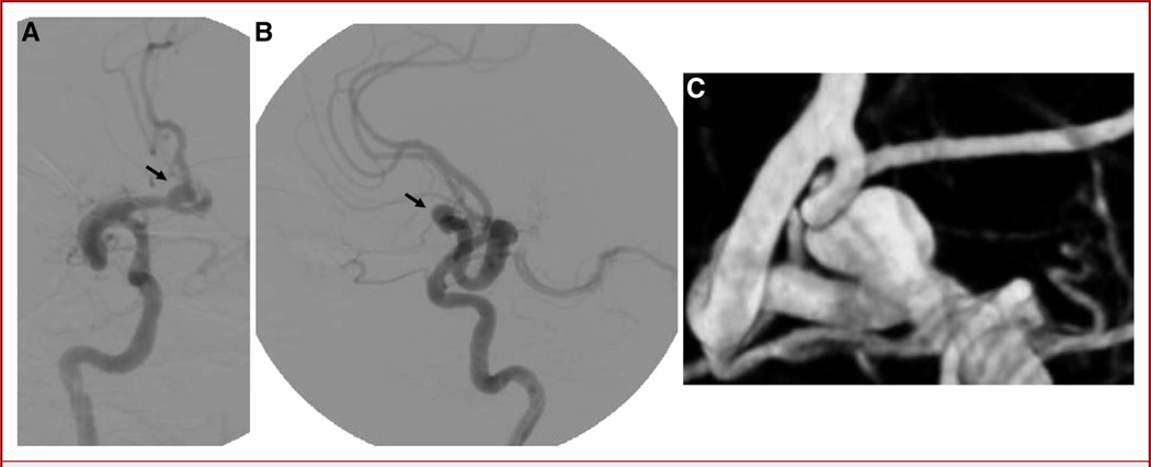
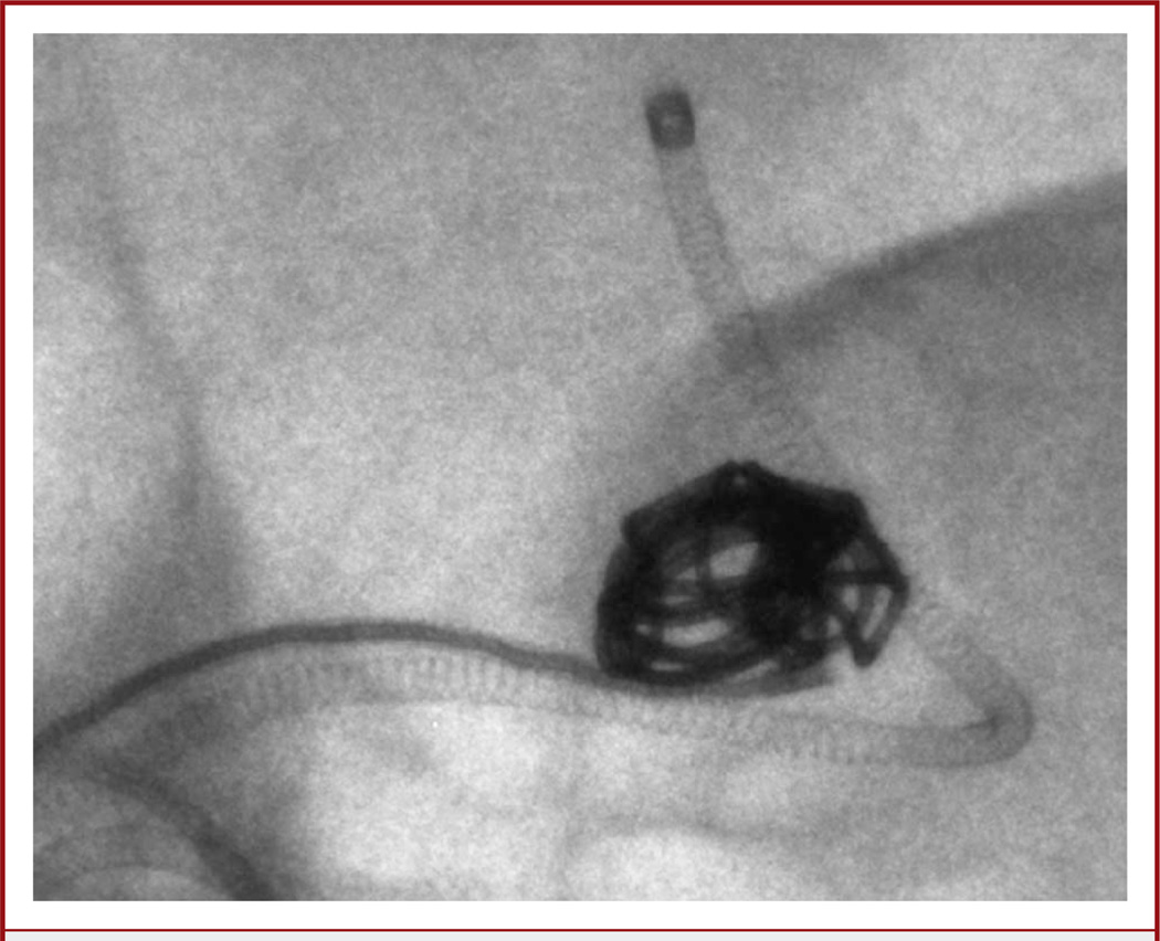
Objective: To detail the use of microangiography performed with a novel fluoroscope during coiling of intracranial aneurysms in 2 separate patients and discuss the benefits and potential limitations of the technology.
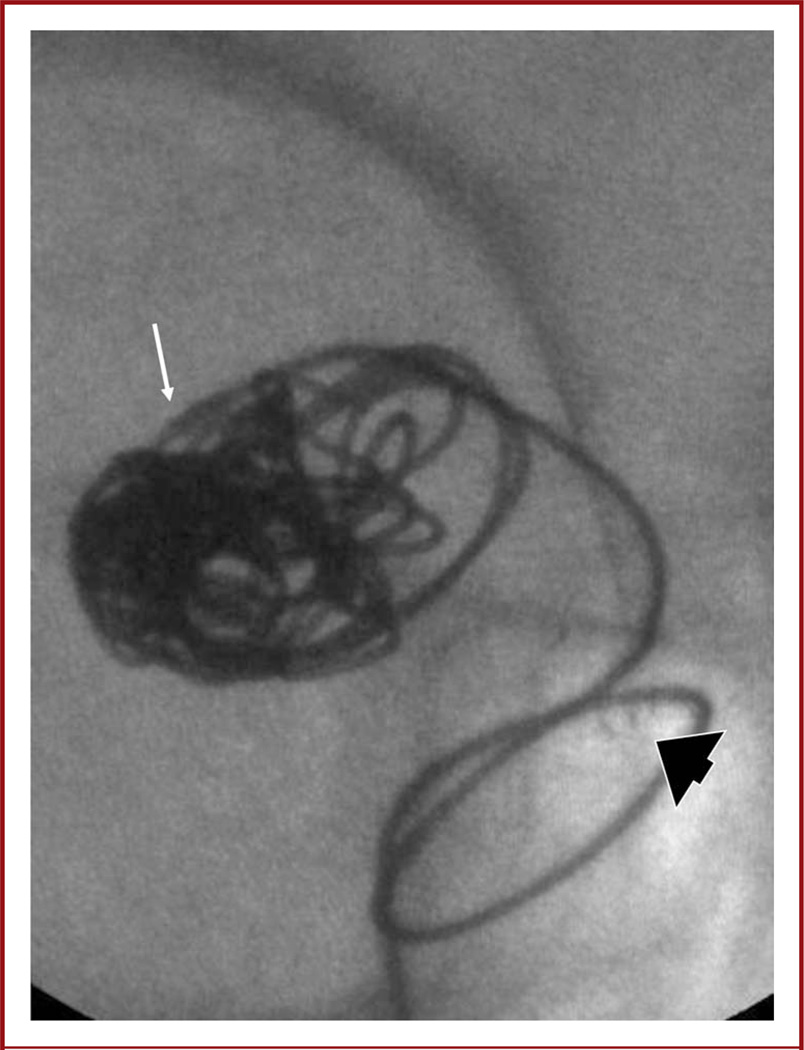
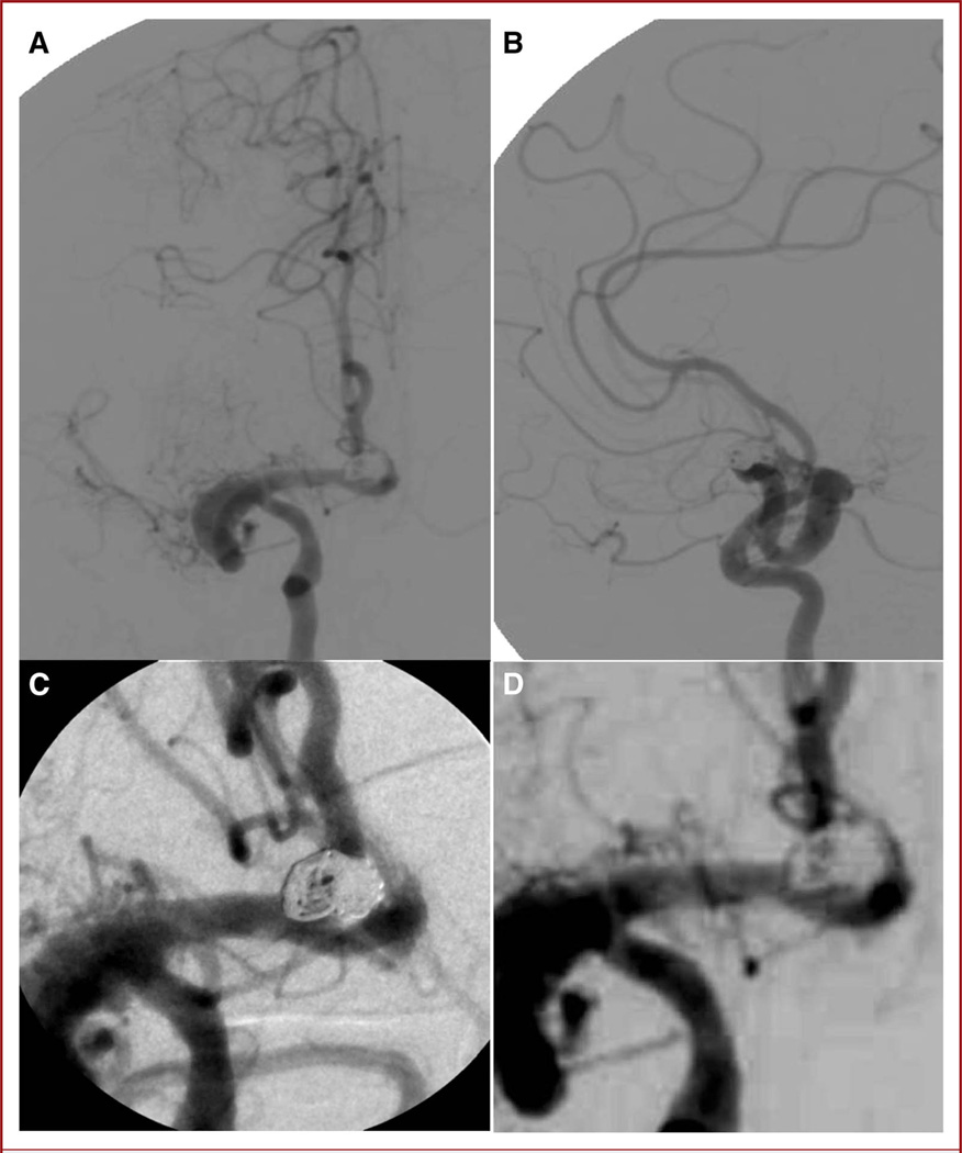
Methods: The microangiographic fluoroscope (MAF) is an ultra high-resolution x-ray detector with superior resolution over a small field of view. The MAF can be incorporated into a standard angiographic C-arm system for use during endovascular procedures.
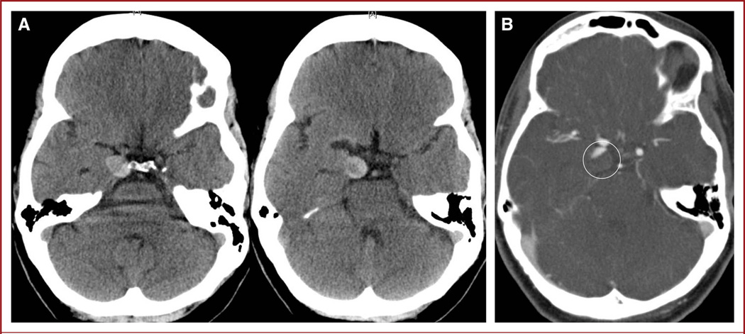
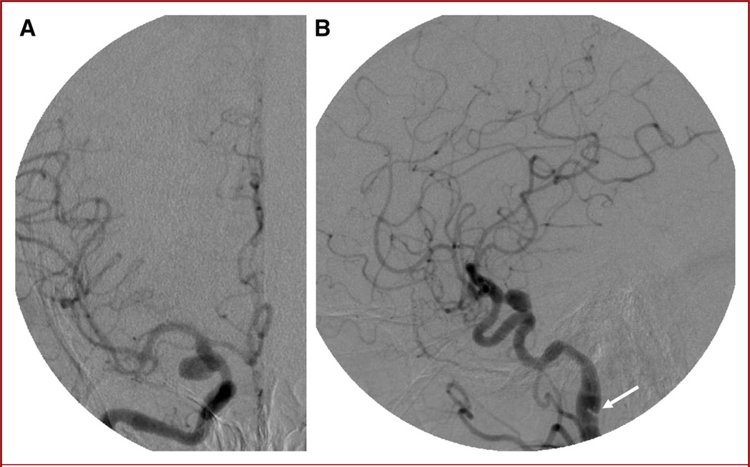
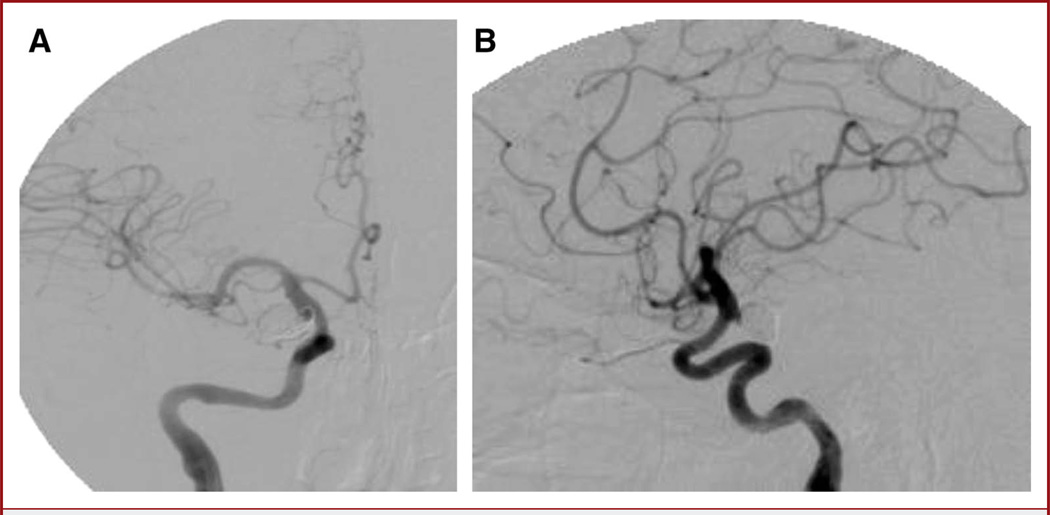
Results: The MAF was useful for improved visualization during endovascular coiling of 2 unruptured intracranial aneurysms, without adding significant time to the procedure. No significant residual aneurysm filling was identified post-coiling, and no complications occurred.
Conclusion: The MAF is a high-resolution detector developed for use in neurointerventional cases in which superior image quality over a small field of view is required. It has been used with success for coiling of 2 unruptured aneurysms at our institution. It shows promise as an important tool in improving the accuracy with which neurointerventionists can perform certain intracranial procedures.
Figures
References
-
- Wang W, Ionita CN, Keleshis C, et al. Progress in the development of a new angiography suite including the high resolution micro-angiographic fluoroscope (MAF), a control, acquisition, processing, and image display system (CAPIDS), and a new detector changer integrated into a commercial C-arm angiography unit to enable clinical use. Proc SPIE. 2010;7622(76225I):pii762251. - PMC - PubMed
-
- Gill K, Bednarek DR, Rudin S. Evaluation of effective dose in region-of-interest neuroimaging (abstract) Med Phys. 2010;37(6):3118.
-
- Mistretta CA, Ort MG, Kelcz F, Cameron JR, Siedband MP, Crummy AB. Absorption edge fluoroscopy using quasi-monoenergetic x-ray beams. Invest Radiol. 1973;8(6):402–412. - PubMed
-
- Mistretta CA, Crummy AB, Strother CM. Digital angiography: a perspective. Radiology. 1981;139(2):273–276. - PubMed
Publication types
MeSH terms
Grants and funding
LinkOut - more resources
Full Text Sources
Medical
