

Review
doi: 10.1259/dmfr/30642039.
Artefacts in CBCT: a review
Affiliations
- PMID: 21697151
- PMCID: PMC3520262
- DOI: 10.1259/dmfr/30642039
Item in Clipboard
Review
Artefacts in CBCT: a review
Dentomaxillofac Radiol.
2011 Jul.
Abstract
Artefacts are common in today's cone beam CT (CBCT). They are induced by discrepancies between the mathematical modelling and the actual physical imaging process. Since artefacts may interfere with the diagnostic process performed on CBCT data sets, every user should be aware of their presence. This article aims to discuss the most prominent artefacts identified in the scientific literature and review the existing knowledge on these artefacts. We also briefly review the basic three-dimensional (3D) reconstruction concept applied by today's CBCT scanners, as all artefacts are more or less directly related to it.
Figures
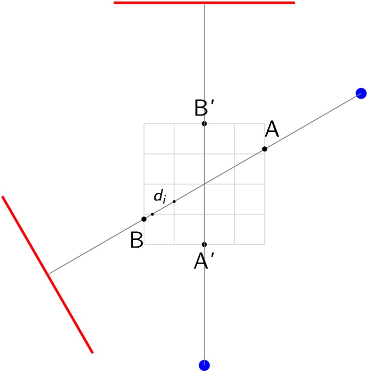
For two arbitrary positions (primed and unprimed) of the unit consisting of a point source (spots) and a detector (line) rotating around a centre of rotation, one exemplary measured “ray” is displayed. It enters the volume to be reconstructed at entry point A (or A′) and exits it in point B (or B′). The distance  the ray traverses through a particular voxel
  provides a simple measurement to compute the contribution of the “ray” to the grey value in voxel
the ray traverses through a particular voxel provides a simple measurement to compute the contribution of the “ray” to the grey value in voxel 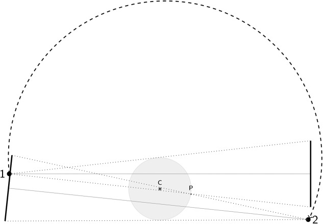
Geometric setting when a smaller detector is applied and the center of rotation (C) is offset relative to the source-detector axis which is aligned with the central X-ray. Note, that only the darker grey-shaded inner circular portion of a circular field of view (FOV) remains in the beam over the entire circle (360°). The light grey-shaded portions of the FOV outside that area are only in the beam over a maximum angular range of 180° plus cone angle (depending on the imaging geometry and their distance from the point of rotation). For a point P located on the outer border of the object, this angle is defined by the two source positions (1,2) displayed here
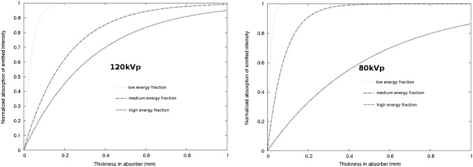
Assuming a simplified polychromatic model with three energetic subfractions for two maximum beam energy settings (120 kVp, left plot, and 80 kVp, right plot), the resulting absorption within gold is plotted vs the absorber thickness for each energy subfraction. Clearly, the lower energetic fractions which contain the maximum of wavelengths in a typical spectrum are massively absorbed by a gold restoration in the beam
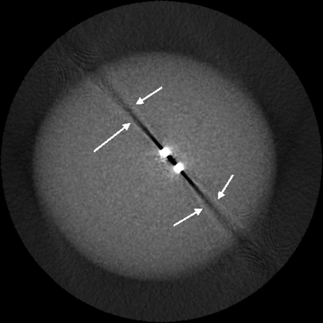
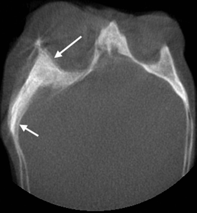
Exponential edge-gradient effect (EEGE) with typical thin lines tangent to sharp edges (arrows) in the direction of the beam
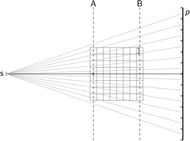
One source of undersampling resulting in aliasing errors in cone beam CT (CBCT) is the cone divergence itself. Obviously, the slice A of the volume nearest to the source s collects many more “rays” per voxel (as measured on the detector pixels, p) than slice B, which is closest to the detector. The number of rays per voxel linearly decreases with the distance of the slice from the source s
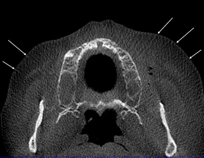
Typical aliasing patterns (Moire patterns) in cone beam CT (CBCT) data sets. The lines (arrows) diverge from the centre towards the periphery and are most probably caused by the undersampling owing to the cone beam geometry illustrated in Figure 5
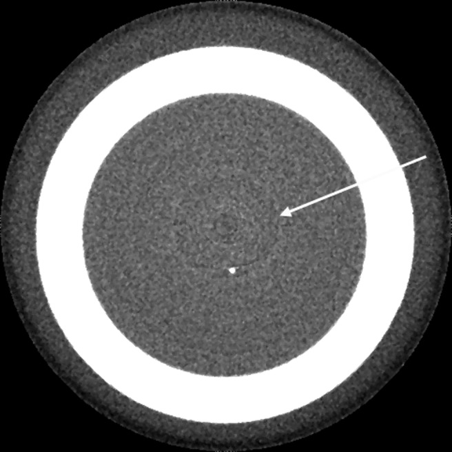
Ring artefacts (arrow) centred around the location of the axis of rotation in the image. As with many other artefacts, they are most clearly visible in axial slices, i.e. in beam direction
Typical double contours (arrows) induced by patient movement during the acquisition process of the projection images
References
-
- Radon J. Über die Bestimmung von Funktionen durch ihre Integralwerte längs gewisser Mannigfaltigkeiten. Ber Verh Sächs Akad Wiss Leipzig, Math Phys Kl 1971;69:262–277
-
- Mueller K. Fast and accurate three-dimensional reconstruction from cone-beam projection data using algebraic methods.1998Ohio, USA: Dissertation at the Ohio State University
-
- Yu L, Pan X, Peliizari CA. Image reconstruction with a shift-variant filtration in circular cone-beam CT. Int J Imaging Syst Technol 2005;14:213–221
-
- Tuy HK. An inversion formula for cone-beam reconstruction. SIAM J Appl Math 1983;43:546–552
-
- Feldkamp LA, Davis LC, Kress JW. Practical cone-beam algorithm. J Opt Soc Am A 1984;1:612–619
Publication types
MeSH terms
LinkOut - more resources
Full Text Sources
Other Literature Sources
