. 2011 Jul 13;475(7355):235-9.
doi: 10.1038/nature10216.

Low-energy control of electrical turbulence in the heart

Affiliations

Low-energy control of electrical turbulence in the heart

Stefan Luther et al. Nature. .

Abstract

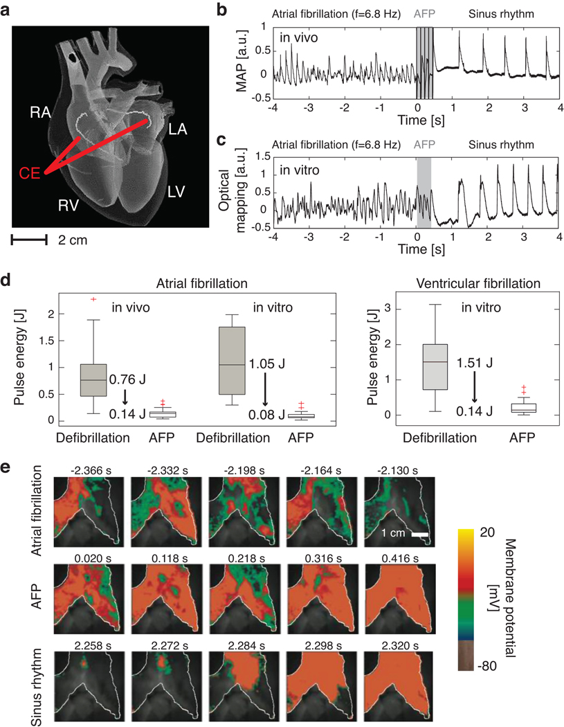
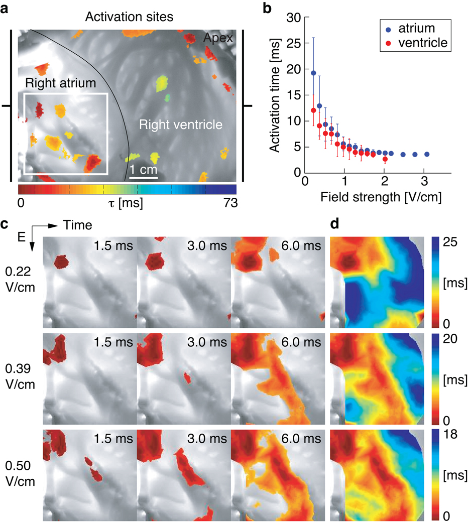
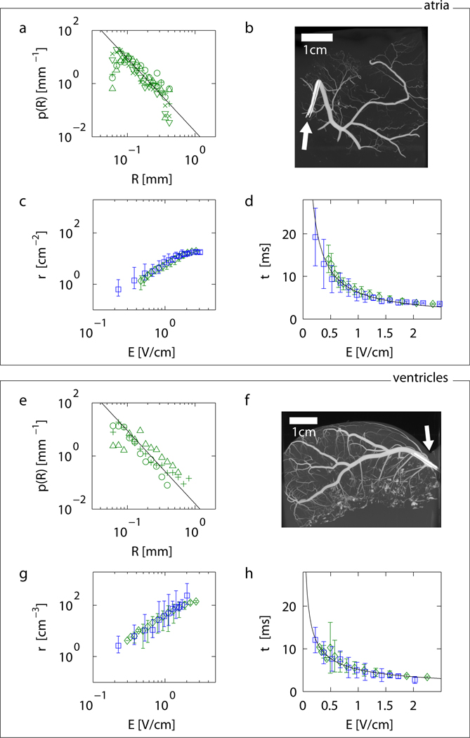
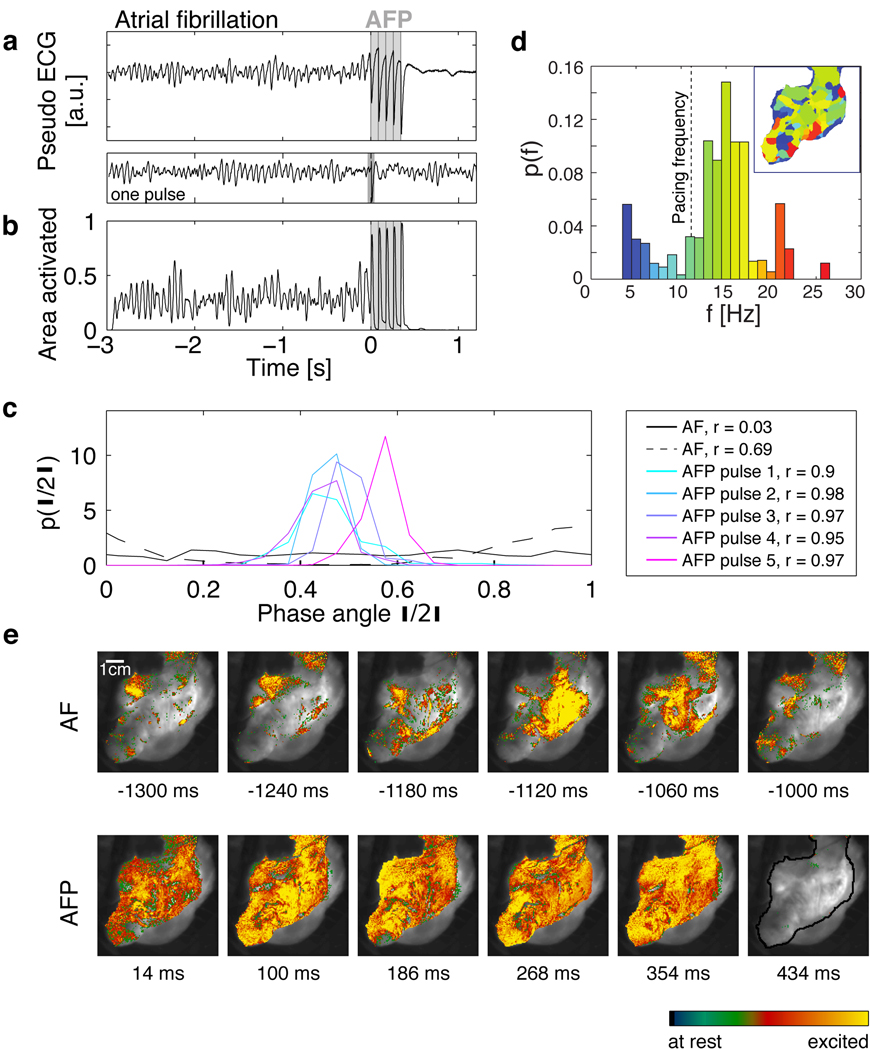
Controlling the complex spatio-temporal dynamics underlying life-threatening cardiac arrhythmias such as fibrillation is extremely difficult, because of the nonlinear interaction of excitation waves in a heterogeneous anatomical substrate. In the absence of a better strategy, strong, globally resetting electrical shocks remain the only reliable treatment for cardiac fibrillation. Here we establish the relationship between the response of the tissue to an electric field and the spatial distribution of heterogeneities in the scale-free coronary vascular structure. We show that in response to a pulsed electric field, E, these heterogeneities serve as nucleation sites for the generation of intramural electrical waves with a source density ρ(E) and a characteristic time, τ, for tissue depolarization that obeys the power law τ ∝ E(α). These intramural wave sources permit targeting of electrical turbulence near the cores of the vortices of electrical activity that drive complex fibrillatory dynamics. We show in vitro that simultaneous and direct access to multiple vortex cores results in rapid synchronization of cardiac tissue and therefore, efficient termination of fibrillation. Using this control strategy, we demonstrate low-energy termination of fibrillation in vivo. Our results give new insights into the mechanisms and dynamics underlying the control of spatio-temporal chaos in heterogeneous excitable media and provide new research perspectives towards alternative, life-saving low-energy defibrillation techniques.


Figures

Figure 1
Figure 1. Low-energy termination of cardiac electrical turbulence in vivo and in vitro
a Schematic of the anatomy of the heart: RA=right atrium, LA=left atrium, RV=right ventricle, LV=left ventricle. A pulsed electric field was applied with standard cardioversion coiled wire electrodes (CE) inserted into the left and right atria by catheters (see SI). b Monophasic Action Potential (MAP) recording of termination of AF using LEAP in vivo. Dominant frequency fv=6.8±0.1Hz, n=5 pulses, pulse duration Δt=8ms, pacing cycle length Tp=99ms, pulse energy E=0.074±0.012J. c Termination of AF in vitro measured from the atrial epicardium of the same heart as in b by optical mapping (see e). The signal from a 0.3×0.3 mm2 region is shown (fv=6.8±0.1Hz, n=5, Δt=8ms, Tp=90ms, E=0.066±0.017J). d Pulse energy reduction of LEAP vs. standard defibrillation. In vivo AF (N=7): LEAP (56 episodes, mean energy Ē=0.14±0.08J); defibrillation (22 episodes, Ē=0.89±0.56J). In vitro AF (N=5): LEAP (46 episodes, Ē=0.10±0.07J); defibrillation (39 episodes, Ē=1.15±0.58J). In vitro ventricular fibrillation (N=7): LEAP (28 episodes, Ē=0.17±0.16J); defibrillation (12 episodes, Ē=1.34±0.89J; see SI). The box plots show the median and the 25th and 75th percentiles. The whiskers indicate the statistically significant data range and red crosses mark outliers. e Optical mapping of the AF termination also shown in panel c. During AF complex spatio-temporal propagation of electrical excitation waves was observed (white line indicates boundary of atrium). LEAP (n=5, Δt=90 ms) progressively synchronized the tissue (movies S1, S2). Data given as mean±standard deviation unless stated otherwise.
Figure 2
Figure 2. Sites of activation in a cardiac preparation
a Canine wedge preparation (7.5×5.6 cm2) consisting of right atrium and right ventricle. At t=0 s an electric field pulse of strength E=0.34 V/cm was applied for 5 ms. The color indicates the time of local activation observed with fluorescence imaging on the endocardium; gray scale trans-illumination image shows its complex anatomy. b Mean activation times τ(E) for atria (blue circles, N=3 preparations, 17 measurements of τ(E)) and ventricles (red circles, N=6 preparations, 24 measurements of τ(E)) in response to an electric field pulse of strength E and duration 5 ms. Error bars indicate the standard deviation. c Activation of the atrium (in the region indicated by the white square in panel a) after an electric field pulse at t=0. With increasing field strength the number of activation sites increased, while the time interval for total activation decreased. The color code for each row is shown in panel d (movie S3). For E<0.2 V/cm no waves were observed. d Isochrone maps of the activation sequences shown in panel c.
Figure 3
Figure 3. From anatomical structure to activation dynamics in atria (a–d) and ventricles (e–h)
a Probability distribution of radii p(R) of canine coronary arteries in atrial tissue obtained from micro-CT measurements (N=5, for symbols see SI). The black line indicates the power law p∝R−2.74±0.05 (mean scaling exponent of all preparations). b,f Example of (b) atrial and (f) ventricular anatomical structure of coronary arteries (movies S9–S10). White arrows indicate the position of the catheters used to inject the contrast agent (see SI). c Density of wave sources derived from Eq. 3 and the atrial measurements shown in panel a (green diamonds) and corresponding density estimated from activation time measurements shown in panel d (blue squares). The predicted density from the structural data in a is plotted as the mean of the predictions from individual preparations. d Atrial activation time measurements using optical mapping (blue squares) and corresponding prediction of activation dynamics (green diamonds) based on the source density obtained in c from the size distribution in a (plotted as the mean of predictions from individual preparations). The black line indicates the power law τ∝E−0.87±0.03 (see Tab. 1 and SI). e Probability distribution p(R) of coronary artery radii for ventricular tissue (N=3). The black line indicates the power law p∝R−2.75±0.3 (mean scaling exponents of all preparations). g Density of wave sources derived from the ventricular measurements shown in panel e (green diamonds), and corresponding density estimated from activation time measurements shown in panel h (blue squares). h Ventricular activation time measurements (blue squares) and prediction of activation times (green diamonds) based on p(R). The black line indicates the power law τ∝E−0.58±0.10 (Tab. 1 and SI). Error bars indicate standard deviation in all plots.
Figure 4
Figure 4. Direct access to vortex cores
a Termination of fibrillation with LEAP. The pseudo ECG is obtained from the optical mapping experiments (see SI). The dominant frequency during AF is fv=15.0±0.5Hz (see inset in d). The vertical gray lines indicate the times at which 5 LEAP pulses (fLEAP=11.8Hz, E=1.96 V/cm) were delivered. A single pulse at this field strength did not terminate fibrillation (pseudo ECG below panel A). Following LEAP normal rhythm is resumed. The termination of fibrillation with fLEAP<fv was observed in atria (N=3, 5 episodes) and ventricles (N=1, 3 episodes). b Area activated indicates tissue synchronization during LEAP. Gray lines indicate timing of LEAP pulses. c Probability distribution of phases θj during AF and for the times of strongest synchronization (maximum order parameter r, see legend) after each LEAP pulse (see SI). During AF, broad phase distributions indicate partial coherence (solid and dashed black lines show two representative distributions). LEAP with fLEAP<fv induces synchronization and thus termination of AF. d Probability distribution of dominant frequencies during AF obtained from optical mapping. The dominant frequency map (inset) shows a complex spatial domain structure corresponding to multiple interacting waves (for color code see histogram; fv=15.0±1.0Hz; fLEAP=11.8±0.5Hz indicated by a vertical dashed line). e Spatio-temporal dynamics during AF, LEAP (images taken at the times of maximum area activated after each pulse; see b), and sinus rhythm (movie S8). The grayscale image shows the atrium (see black line in the last image; 70×70 mm2). The last image shows quiescence after AF termination.

Comment in

References

    1. Davidenko JM, Pertsov AV, Salomonsz R, Baxter W, Jalife J. Stationarity and drifting spiral waves of excitation in isolated cardiac muscle. Nature. 1992;355:349–351. - PubMed
    1. Gray RA, Pertsov AM, Jalife J. Spatial and temporal organization during cardiac fibrillation. Nature. 1998;392:75–78. - PubMed
    1. Witkowski FX, et al. Spatiotemporal evolution of ventricular fibrillation. Nature. 1998;392:78–82. - PubMed
    1. Cherry EM, Fenton FH. Visualization of spiral and scroll waves in simulated and experimental cardiac tissue. New J. Phys. 2008;10:125016–125059.
    1. Koster RW, et al. A randomized trial comparing monophasic and biphasic waveform shocks for external cardioversion of atrial fibrillation. Am. Heart J. 2004;147:e1–e7. - PubMed

Publication types