Review
. 2011 Nov;82(3):210-20.
doi: 10.1016/j.mvr.2011.06.013. Epub 2011 Jul 2.

Microfluidic devices for modeling cell-cell and particle-cell interactions in the microvasculature

Affiliations
Review

Microfluidic devices for modeling cell-cell and particle-cell interactions in the microvasculature

Balabhaskar Prabhakarpandian et al. Microvasc Res. 2011 Nov.

Abstract

Cell-fluid and cell-cell interactions are critical components of many physiological and pathological conditions in the microvasculature. Similarly, particle-cell interactions play an important role in targeted delivery of therapeutics to tissue. Development of in vitro fluidic devices to mimic these microcirculatory processes has been a critical step forward in our understanding of the inflammatory process, developing of nano-particulate drug carriers, and developing realistic in vitro models of the microvasculature and its surrounding tissue. However, widely used parallel plate flow based devices and assays have a number of important limitations for studying the physiological conditions in vivo. In addition, these devices are resource hungry and time consuming for performing various assays. Recently developed, more realistic, microfluidic based devices have been able to overcome many of these limitations. In this review, an overview of the fluidic devices and their use in studying the effects of shear forces on cell-cell and cell-particle interactions is presented. In addition, use of mathematical models and computational fluid dynamics (CFD) based models for interpreting the complex flow patterns in the microvasculature is highlighted. Finally, the potential of 3D microfluidic devices and imaging for better representing in vivo conditions under which cell-cell and cell-particle interactions take place is discussed.


Figures

Figure 1
Figure 1
Particle Adhesion Process
  1. Schematic of the leukocyte adhesion process. Leukocytes roll on the endothelium followed by adhesion, spreading and subsequent migration into the tissue space

  2. Example of a common biophysical process during cell Cells/particles adhere when the adhesive forces are equal or greater than the hydrodynamic forces acting on the cell. Although the illustration shows the hydrodynamic force parallel to the surface, the realized force may have a new orientation following rolling the adhesive forces formed between the ligand and receptors will not necessarily be normal to the surface at all times during the adhesion process.
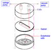
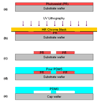
Figure 2
Figure 2
Schematic of the Glycotech Flow Chamber for studying cellular interaction.
Figure 3
Figure 3
Fabrication Process of PDMS devices by soft-lithography: (a) Spin-coating of photoresist (PR); (b) UV photolithography of the PR; (c) Development of the PR; (d) PDMS casting over developed PR, followed by PDMS curing; and (e) PDMS bonding to a cap (microscope slides, coverslip, glass, etc.)
Figure 4
Figure 4
Idealized Microfluidic Devices currently on the Market
  1. µ-Slide (Ibidi LLC) for adhesion assays

  2. Fluxion Biosciences Well plate based high-throughput assay for adhesion assays

(Reproduced with permission from Ibidi LLC and Fluxion Biosciences)
Figure 5
Figure 5
(a) Schematic of the circular channels fabrication process. (b and c) Picture of a 100 µm × 100µm microchannel before and after treatment. (d) Picture of 100 µm × 100µm channel after coating it three times with liquid PDMS [Abdelgawad et al., 2010]-Reproduced by permission of The Royal Society of Chemistry, http://dx.doi.org/10.1039/c0lc00093k
Figure 6
Figure 6
Particle adhesion profiles at the bifurcation and linear sections of a microfluidic device. (a) adhesion patterns of spherical particles (b) adhesion patterns of elliptical particles. Reprinted from J Control Release. Sep 1;146 (2), Doshi et al., Flow and adhesion of drug carriers in blood vessels depend on their shape: a study using model synthetic microvascular networks. 196–200 2010 with permission from Elsevier.
Figure 7
Figure 7
Synthetic Microvascular Network (SMN) based microfluidic chip (a). Image of microvascular network in-vivo perfused with fluorescent rhodamine (b). Digitized AutoCAD image of microvascular network in panel “a” (c). Microfluidic chip perfused with fluorescent dye, (d). Microfluidic chip with perfused fluorescent particles. Intensity of the fluorescent images in panels a, c, and d have been digitally enhanced to better highlight the microvessels/microchannels.
Figure 8
Figure 8
Transient perfusion studies comparing experimental and simulation results in SMN. (panels A–C) experiments and (panels D–F) CFD simulation. The scale for simulation is an arbitrary unit with blue (no perfusion; 0) and magenta (complete perfusion; 1). Experimental and simulation results show very good comparison with each other. (With kind permission from Springer Science+Business Media:Biomed Microdevices, Synthetic microvascular networks for quantitative analysis of particle adhesion, Aug 10(4), 2008, 585–95, Prabhakarpandian et al., Figure 4)
Figure 9
Figure 9
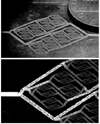
(Top panel) Eight level multi-width multi-level microvasculature network with microchannels fabricated by one-step laser direct write. (Bottom panel) Image showing the difference in intensity levels corresponding to different channel depths [Lim et al., 2003]-Reproduced by permission of The Royal Society of Chemistry, http://dx.doi.org/10.1039/B308452C
Figure 10
Figure 10
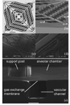
Design of lung vascular network with physiologic blood flow. (a) Top view of high density vascular network design, (b) isometric view of SolidWorks rendering of mold demonstrating variable depths and 1 : 1 aspect ratios of all channels, (c) SEM of smallest channels of device, (d) SEM of transition between large inlet channel and branch channel demonstrating precise 3D fillets achieved with micro machined mold. Scale bar in (a, c, d) =1 cm. (e) Isometric cross-sectional view SEM of the device showing the three components of the device; alveolar chamber, gas exchange membrane and vascular network. Scale bar (e) = 100µm [Hoganson et al., 2011]-Reproduced by permission of The Royal Society of Chemistry, http://dx.doi.org/10.1039/C0LC00158A

References

    1. Abdelgawad M, Wu C, Chien WY, Geddie WR, Jewett MA, Sun Y. A fast and simple method to fabricate circular microchannels in polydimethylsiloxane (PDMS) Lab Chip. 7. 2011;11(3):545–551. - PubMed
    1. Agrawal N, Toner M, Irimia D. Neutrophil migration assay from a drop of blood. Lab Chip. 2008;8(12):2054–2061. - PMC - PubMed
    1. Aigner S, Ramos CL, Hafezi-Moghadam A, Lawrence MB, Friederichs J, Altevogt P, Ley K. CD24 mediates rolling of breast carcinoma cells on P-selectin. FASEB J. 1998;12(12):1241–1251. - PubMed
    1. Alves CS, Burdick MM, Thomas SN, Pawar P, Konstantopoulos K. The dual role of CD44 as a functional P-selectin ligand and fibrin receptor in colon carcinoma cell adhesion. Am J Physiol Cell Physiol. 2008;294(4):C907–C916. - PubMed
    1. Anderson JR, Chiu DT, Jackman RJ, Cherniavskaya O, McDonald JC, Wu H, Whitesides SH, Whitesides GM. Fabrication of topologically complex three-dimensional microfluidic systems in PDMS by rapid prototyping. Anal Chem 15. 2000;72(14):3158–3164. - PubMed

Publication types

LinkOut - more resources