. 2011:2011:236854.
doi: 10.1155/2011/236854. Epub 2011 Jun 13.

Development of a New Tool for 3D Modeling for Regenerative Medicine

Affiliations

Development of a New Tool for 3D Modeling for Regenerative Medicine

Filippo Mattoli et al. Int J Biomed Imaging. 2011.

Abstract

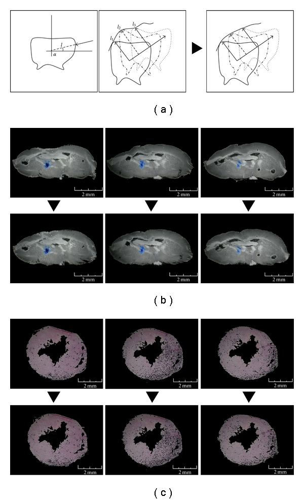
The effectiveness of therapeutic treatment based on regenerative medicine for degenerative diseases (i.e., neurodegenerative or cardiac diseases) requires tools allowing the visualization and analysis of the three-dimensional (3D) distribution of target drugs within the tissue. Here, we present a new computational procedure able to overcome the limitations of visual analysis emerging by the examination of a molecular signal within images of serial tissue/organ sections by using the conventional techniques. Together with the 3D anatomical reconstitution of the tissue/organ, our framework allows the detection of signals of different origins (e.g., marked generic molecules, colorimetric, or fluorimetric substrates for enzymes; microRNA; recombinant protein). Remarkably, the application does not require the employment of specific tracking reagents for the imaging analysis. We report two different representative applications: the first shows the reconstruction of a 3D model of mouse brain with the analysis of the distribution of the β-Galactosidase, the second shows the reconstruction of a 3D mouse heart with the measurement of the cardiac volume.


Figures

Figure 1
Figure 1
Soil and glare reduction. Soils and glares have been removed in order to have a clear vision of the final model. (a) We have on the left the original image of the section of brain tissue, and on the right the image after soil and glare reduction. (b) The same procedure has been used for heart section images.
Figure 2
Figure 2
Woven image centre. (a) Outline (the reported image doesn't represent any specific tissue section) of the image centring routine (see routine 1). x n  and y n are coordinates of not black pixels (not RBG 0,0,0), x 0 and y 0 are the centre of the bitmap coordinates. The program calculates a kind of barycentre of the woven area in the image and moves it to the centre of the bitmap. (b) Example of the image centring procedure: left panel is an original image of the coronal serial sections, right panel is the same image after the automatic woven centring. (c) Example of the image centring procedure for heart section images.
Figure 3
Figure 3
Woven image orientation. (a) Outline of the image orienting routine (see routine 2). The images of the woven area were oriented regarding the adjacent slides by the routine that rotates the woven area of the bitmap 360°, then it chooses the angle where the differences between the adjacent images are the smallest, and hence, the images are the most similar. i is the intensity of the pixel number of the first image and k is the intensity of the pixel n of the previous image. The image chosen is the one with the smallest value of d. (b) Example of the image-orienting procedure: In the panels we can see two of the images obtained from the brain serial sections that are rotated with respect to the adjacent image. (c) The same procedure has been used for the heart section images.
Figure 4
Figure 4
Reduction of the tissue deformation. (a) Outline of the tissue deformation routine (see routine 3). The discontinuity between the sections is diminished by the calculation of the medium of the contours. l n is the distance between the contour pixel and the centre of the bitmap of the n serial section for the angle α. With the distance of the contour pixels, the internal area pixels of the section are also adjusted by a proportional linear correction. (b) The images represent three original sequential sections of the brain. In the images below, the deformations have been reduced in order to carry out sequential images which are more homogenous. (c) The images represent three original sequential sections of the heart.
Figure 5
Figure 5
3D views of the brain model. (a) Superior view of the model. (b) Isometric view of the horizontal section of the brain model. In this image we can see the internal structure of the mouse brain and the distance from the external of the brain to the injection point. (c) Isometric view of the full model.
Figure 6
Figure 6
Representative sections of HSV-T0Z distribution in the mouse central nervous system. Serial brain sections were produced dissecting animals in coronal orientations (a–e). Here, we show a part of the representative coronal sections. Sections were stained with the X-Gal substrate (blue signal) as described in method paragraph. In the dark field (DF) images are indicated the magnification and measurement bars. Point of injection is shown (red arrow) into image (a) on the left hemisphere close to bregma line. In (e) there is a representative section of cerebellum.
Figure 7
Figure 7
Isolation of the X-Gal staining. An isometric view with the distribution of the X-Gal staining (in red) is shown, highlighting a magnification of the signal. The model has been rendered with a demo version of VolView 2.0 produced by Kitware, USA.
Figure 8
Figure 8
3D views of the heart model. (a) Isometric view of the whole heart model. (b) Isometric view of the horizontal section of the heart model. (c) Isometric view of the vertical section of the heart model. In this image, we can see the ventricles of the mouse heart and the thickness of the heart walls.

Similar articles

References

    1. Martino S, D’Angelo F, Armentano I, et al. Hydrogenated amorphous carbon nanopatterned film designs drive human bone marrow mesenchymal stem cell cytoskeleton architecture. Tissue Engineering. Part A. 2009;15(10):3139–3149. - PubMed
    1. Martino S, di Girolamo I, Orlacchio A, Datti A, Orlacchio A. MicroRNA implications across neurodevelopment and neuropathology. Journal of Biomedicine and Biotechnology. 2009;2009:13 pages. Article ID 654346. - PMC - PubMed
    1. Martino S, di Girolamo I, Cavazzin C, et al. Neural precursor cell cultures from GM2 gangliosidosis animal models recapitulate the biochemical and molecular hallmarks of the brain pathology. Journal of Neurochemistry. 2009;109(1):135–147. - PubMed
    1. Quattrocelli M, Cassano M, Crippa S, Perini I, Sampaolesi M. Cell therapy strategies and improvements for muscular dystrophy. Cell Death and Differentiation. 2010;17(8):1222–1229. - PubMed
    1. Lattanzi A, Neri M, Maderna C, et al. Widespread enzymatic correction of CNS tissues by a single intracerebral injection of therapeutic lentiviral vector in leukodystrophy mouse models. Human Molecular Genetics. 2010;19(11):2208–2227. - PubMed

LinkOut - more resources