. 2012 May;67(5):1237-51.
doi: 10.1002/mrm.23101. Epub 2011 Aug 8.

Hybrid prospective and retrospective head motion correction to mitigate cross-calibration errors

Affiliations

Hybrid prospective and retrospective head motion correction to mitigate cross-calibration errors

Murat Aksoy et al. Magn Reson Med. 2012 May.

Abstract

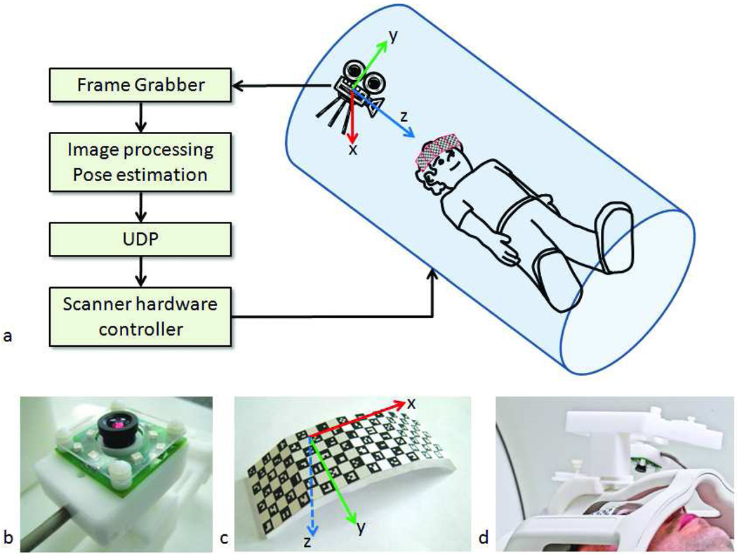
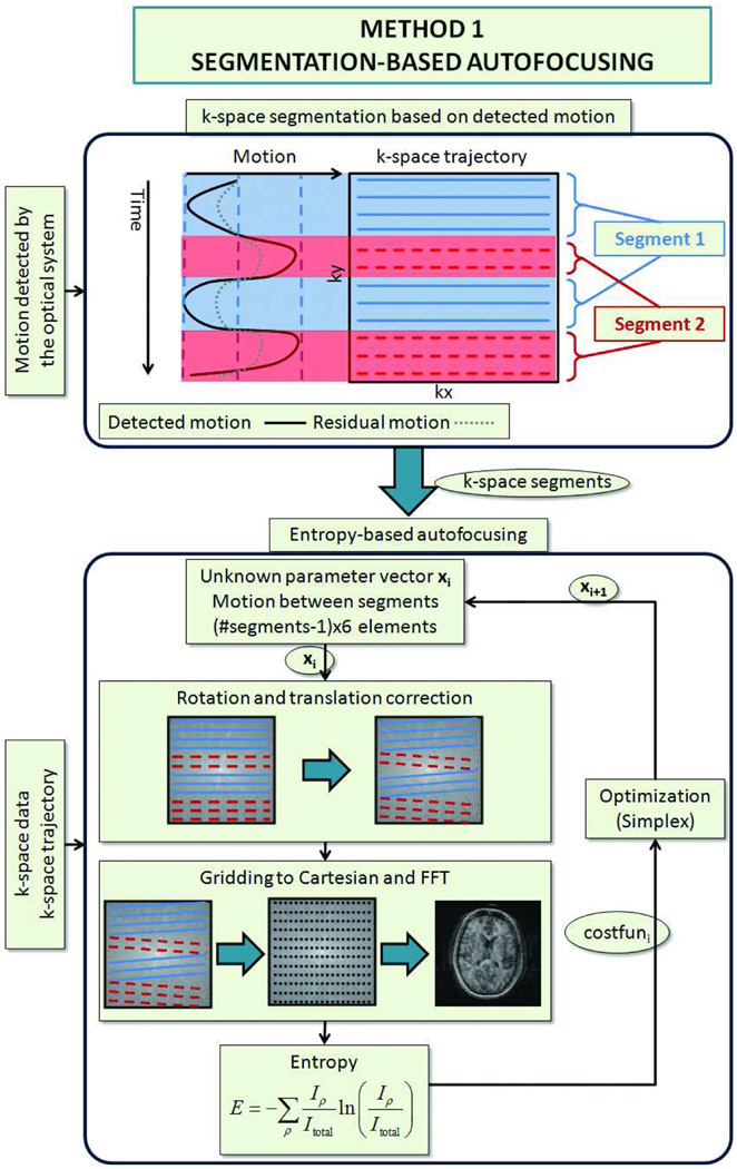
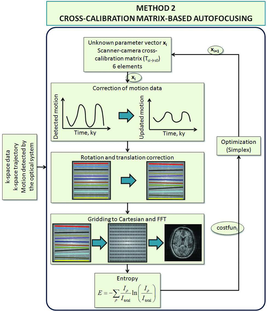
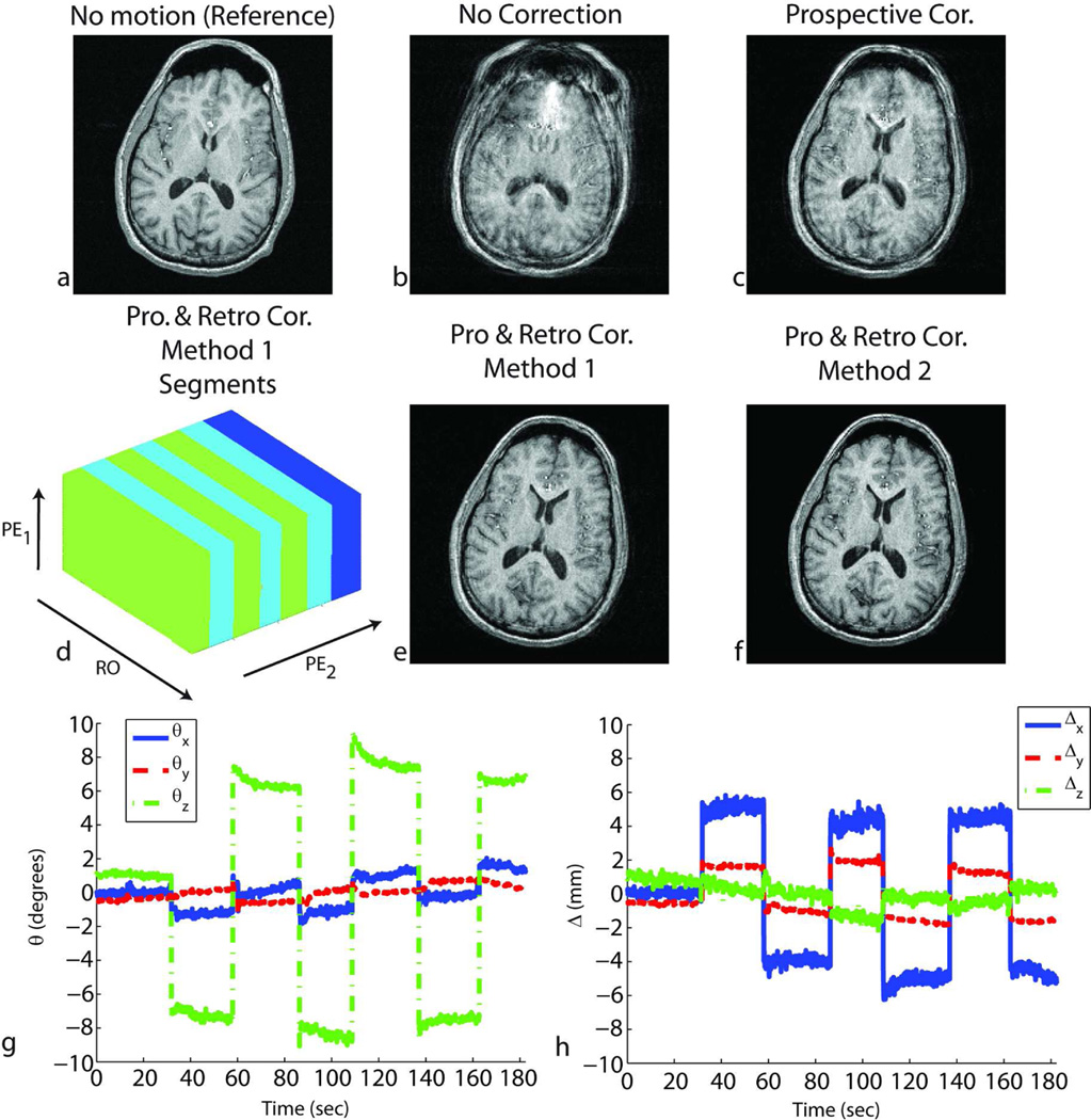
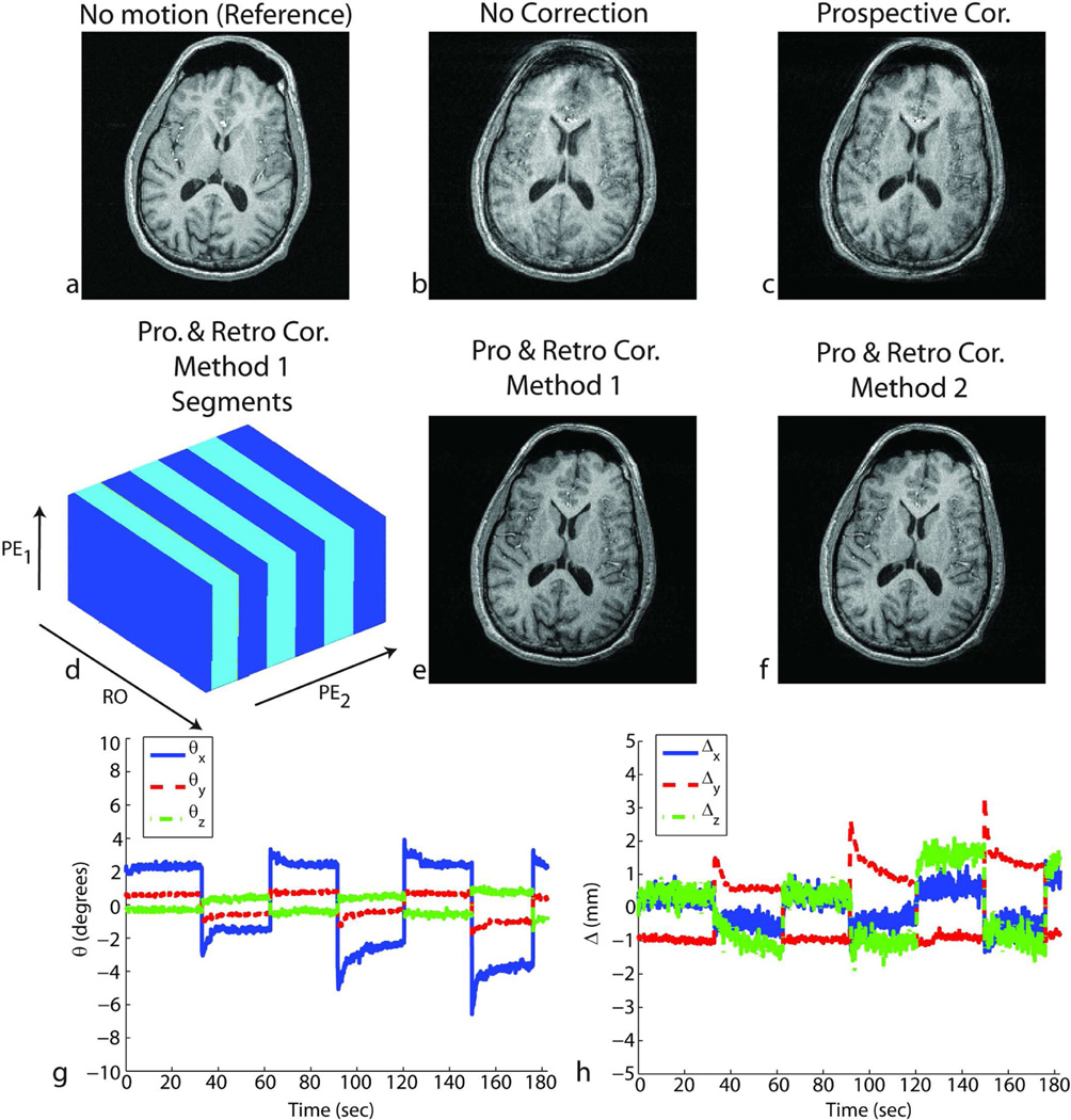
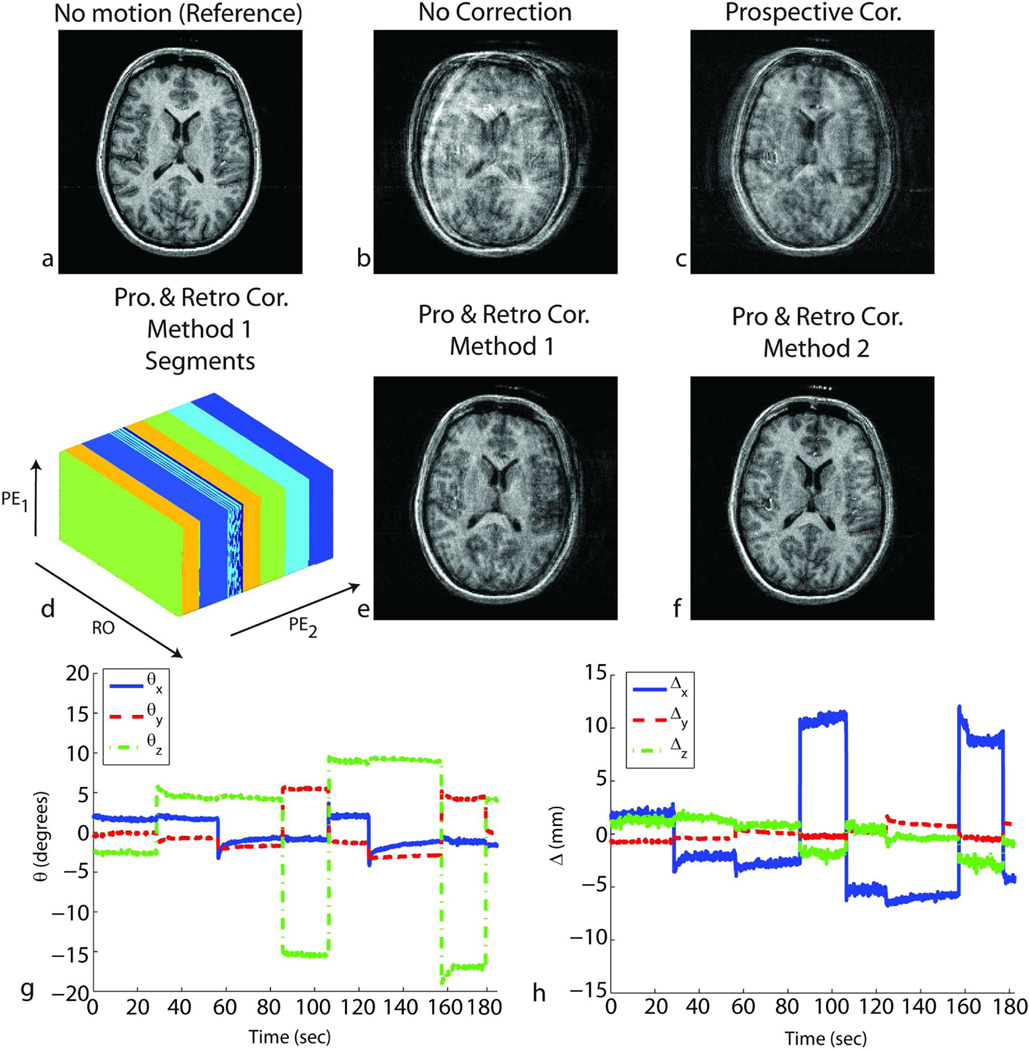
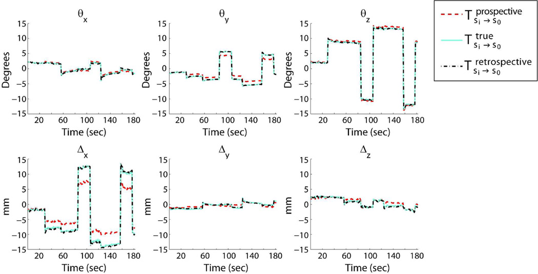
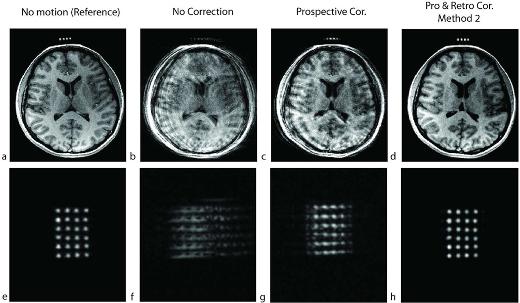
Utilization of external motion tracking devices is an emerging technology in head motion correction for MRI. However, cross-calibration between the reference frames of the external tracking device and the MRI scanner can be tedious and remains a challenge in practical applications. In this study, we present two hybrid methods, both of which combine prospective, optical-based motion correction with retrospective entropy-based autofocusing to remove residual motion artifacts. Our results revealed that in the presence of cross-calibration errors between the optical tracking device and the MR scanner, application of retrospective correction on prospectively corrected data significantly improves image quality. As a result of this hybrid prospective and retrospective motion correction approach, the requirement for a high-quality calibration scan can be significantly relaxed, even to the extent that it is possible to perform external prospective motion tracking without any prior cross-calibration step if a crude approximation of cross-calibration matrix exists. Moreover, the motion tracking system, which is used to reduce the dimensionality of the autofocusing problem, benefits the retrospective approach at the same time.


Figures

Figure 1
Figure 1
System setup. An MR-compatible camera was mounted on the head coil inside the scanner bore (a,d). The camera (b) took images of a self-encoded marker (c) that was attached to the patient's forehead. These images were processed by an external laptop where 1) the squares on the marker were segmented out; 2) the pose of the marker was estimated; and 3) the 6 parameters (i.e. 3 rotations and 3 translations) to update the scanner geometry were sent to the scanner RF and gradient hardware controller. This allowed the scan plane to follow the subject's head in real-time.
Figure 2
Figure 2
Segmentation based autofocusing algorithm. The motion information obtained from the motion tracking system is shown in black (upper part of the figure). Due to errors in cross-calibration, this tracking information is not 100% accurate, and residual error remains on the k-space data, which is shown with a dotted line. To eliminate this residual error, first, the k-space data was divided into segments using the tracking information provided by the optical system. Inside these segments, the patient position was assumed to be the same. Next, only the motion between the segments was determined using iterative entropy-based autofocusing algorithm.
Figure 3
Figure 3
Cross-calibration matrix based autofocusing algorithm. In this method, the residual error on the k-space data was assumed to originate from the inaccuracies in the scanner-camera cross-calibration matrix. Thus, the residual motion between each k-space line was a function of the difference between the used and corrected cross-calibration matrices. So, in this method, the cross-calibration matrix was optimized to find the image with minimum entropy.
Figure 4
Figure 4
Results of in-vivo experiments in the presence of shaking motion (around the S/I axis of the subject) throughout the scan for subject 1. Without correction, the reconstructed image shows motion-related blurring (b). After prospective correction, residual artifacts remained due to the inaccurate cross-calibration between camera and scanner references frames (c). Retrospective correction using either method 1 – segmented autofocusing (e) or method 2 – cross-calibration matrix-based autofocusing (f) improved the image quality. For method 1, the k-space segments in which the head position was approximately the same are shown in (d). RO corresponds to the readout axis, and PE1 and PE2 correspond to fast and slow phase encoding axes, respectively. The rotations (g) and translations (h) performed by the volunteer are also shown.
Figure 5
Figure 5
Results of in-vivo experiments in the presence of nodding motion (around the R/L axis of the subject) throughout the scan for subject 1. Without correction, the reconstructed image showed motion-related blurring (b). After prospective correction, residual artifacts remain due to the inaccurate cross-calibration between camera and scanner reference frames (c). Retrospective correction using either method 1 – segmented autofocusing (e) or method 2 – cross-calibration matrix-based autofocusing (f) improved the image quality. For method 1, the k-space segments in which the head position was approximately the same are shown in (d). RO corresponds to the readout axis, and PE1 and PE2 correspond to fast and slow phase encoding axes, respectively. The rotations (g) and translations (h) performed by the volunteer are also shown.
Figure 6
Figure 6
Results of in-vivo experiments in the presence of shaking and nodding motion throughout the scan for subject 2. Without correction, the reconstructed image shows motion-related blurring (b). After prospective correction, residual artifacts remain due to the inaccurate cross-calibration between camera and scanner reference frames (c). Retrospective correction using method 2 – cross-calibration matrix-based autofocusing (f) improved the image quality. However, due to the large number of unknowns caused by the complicated motion pattern, method 1-segmentation based autofocusing did not yield good image quality (e). For method 1, the k-space segments in which the head position was approximately the same are shown in (d). RO corresponds to the readout axis, and PE1 and PE2 correspond to fast and slow phase encoding axes, respectively. Some of the estimated locations can fall onto the border separating two segments, which explains the color pattern observed on segment 3. The rotations (g) and translations (h) performed by the volunteer are also shown.
Figure 7
Figure 7
Motion plots comparing the true, prospective and retrospective motion parameters. The true motion was calculated using the true cross-calibration matrix. The retrospective motion was determined after retrospective correction using cross-calibration matrix based autofocusing. It can be seen that the retrospective motion is very similar to the true motion.
Figure 8
Figure 8
Results of a high-resolution (256×256×192) in-vivo experiment in the presence of shaking motion throughout the scan for subject 6. The resolution in this scan is similar to what would be used for a cross-calibration scan. a–d show an axial slice and e–f show an oblique slice that goes through the agar droplets. The non-corrected image showed motion artifacts and the agar droplets were not identifiable in (b) and (f). After prospective correction, the artifacts remained because the true cross-calibration between the camera and the scanner was unknown (c,g). After retrospective correction using method 2, the agar droplets were distinguishable, and could be used to perform the cross-calibration (d,h).
Figure 9
Figure 9
The value of the cost function (i.e. entropy) as a function of the iteration number. (a) The iterations for the experiment given in Fig. 4 (subject 1) and (b) Fig. 6 (subject 2) are shown. For the case with multiple in-plane rotations, the convergence of method 2 was faster than method 1 (a) due to the lower number of unknowns. For the case with more complicated motion where the subject performed both shaking and nodding, it was observed that the segmentation based autofocusing did not converge during 200 iterations to yield adequate image quality (b). This was due to the high number of segments, and thus, the high number of unknowns (Fig. 6d). However, cross-calibration matrix based autofocusing had a fast convergence rate in this case. Given 200 iterations, the total computation time was around 2 hours.

References

    1. Thesen S, Heid O, Mueller E, Schad LR. Prospective acquisition correction for head motion with image-based tracking for real-time fMRI. Magn Reson Med. 2000;44(3):457–465. - PubMed
    1. van der Kouwe AJ, Benner T, Dale AM. Real-time rigid body motion correction and shimming using cloverleaf navigators. Magn Reson Med. 2006;56(5):1019–1032. - PubMed
    1. Ooi MB, Krueger S, Thomas WJ, Swaminathan SV, Brown TR. Prospective real-time correction for arbitrary head motion using active markers. Magn Reson Med. 2009;62(4):943–954. - PMC - PubMed
    1. Dold C, Zaitsev M, Speck O, Firle EA, Hennig J, Sakas G. Prospective head motion compensation for MRI by updating the gradients and radio frequency during data acquisition. Med Image Comput Comput Assist Interv. 2005;8(Pt 1):482–489. - PubMed
    1. Dold C, Zaitsev M, Speck O, Firle EA, Hennig J, Sakas G. Advantages and limitations of prospective head motion compensation for MRI using an optical motion tracking device. Acad Radiol. 2006;13(9):1093–1103. - PubMed