Comparison of ring artifact removal methods using flat panel detector based CT images
- PMID: 21846411
- PMCID: PMC3201024
- DOI: 10.1186/1475-925X-10-72
Comparison of ring artifact removal methods using flat panel detector based CT images
Abstract
Background: Ring artifacts are the concentric rings superimposed on the tomographic images often caused by the defective and insufficient calibrated detector elements as well as by the damaged scintillator crystals of the flat panel detector. It may be also generated by objects attenuating X-rays very differently in different projection direction. Ring artifact reduction techniques so far reported in the literature can be broadly classified into two groups. One category of the approaches is based on the sinogram processing also known as the pre-processing techniques and the other category of techniques perform processing on the 2-D reconstructed images, recognized as the post-processing techniques in the literature. The strength and weakness of these categories of approaches are yet to be explored from a common platform.
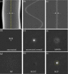
Method: In this paper, a comparative study of the two categories of ring artifact reduction techniques basically designed for the multi-slice CT instruments is presented from a common platform. For comparison, two representative algorithms from each of the two categories are selected from the published literature. A very recently reported state-of-the-art sinogram domain ring artifact correction method that classifies the ring artifacts according to their strength and then corrects the artifacts using class adaptive correction schemes is also included in this comparative study. The first sinogram domain correction method uses a wavelet based technique to detect the corrupted pixels and then using a simple linear interpolation technique estimates the responses of the bad pixels. The second sinogram based correction method performs all the filtering operations in the transform domain, i.e., in the wavelet and Fourier domain. On the other hand, the two post-processing based correction techniques actually operate on the polar transform domain of the reconstructed CT images. The first method extracts the ring artifact template vector using a homogeneity test and then corrects the CT images by subtracting the artifact template vector from the uncorrected images. The second post-processing based correction technique performs median and mean filtering on the reconstructed images to produce the corrected images.
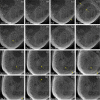
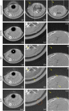
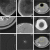
Results: The performances of the comparing algorithms have been tested by using both quantitative and perceptual measures. For quantitative analysis, two different numerical performance indices are chosen. On the other hand, different types of artifact patterns, e.g., single/band ring, artifacts from defective and mis-calibrated detector elements, rings in highly structural object and also in hard object, rings from different flat-panel detectors are analyzed to perceptually investigate the strength and weakness of the five methods. An investigation has been also carried out to compare the efficacy of these algorithms in correcting the volume images from a cone beam CT with the parameters determined from one particular slice. Finally, the capability of each correction technique in retaining the image information (e.g., small object at the iso-center) accurately in the corrected CT image has been also tested.
Conclusions: The results show that the performances of the algorithms are limited and none is fully suitable for correcting different types of ring artifacts without introducing processing distortion to the image structure. To achieve the diagnostic quality of the corrected slices a combination of the two approaches (sinogram- and post-processing) can be used. Also the comparing methods are not suitable for correcting the volume images from a cone beam flat-panel detector based CT.
Figures


Similar articles
-
High-quality 3D correction of ring and radiant artifacts in flat panel detector-based cone beam volume CT imaging.Phys Med Biol. 2011 Oct 7;56(19):6495-519. doi: 10.1088/0031-9155/56/19/020. Epub 2011 Sep 20. Phys Med Biol. 2011. PMID: 21934193
-
A new iterative algorithm for ring artifact reduction in CT using ring total variation.Med Phys. 2019 Nov;46(11):4803-4815. doi: 10.1002/mp.13762. Epub 2019 Sep 20. Med Phys. 2019. PMID: 31408539 Free PMC article.
-
Removal of ring artifacts in CT imaging through detection and correction of stripes in the sinogram.Phys Med Biol. 2010 Nov 21;55(22):6911-30. doi: 10.1088/0031-9155/55/22/020. Epub 2010 Nov 3. Phys Med Biol. 2010. PMID: 21048294
-
CT artifact correction for sparse and truncated projection data using generative adversarial networks.Med Phys. 2021 Feb;48(2):615-626. doi: 10.1002/mp.14504. Epub 2020 Dec 30. Med Phys. 2021. PMID: 32996149 Review.
-
Progress and Challenges in Physiological Artifacts' Detection in Electroencephalographic Readings.Curr Med Imaging. 2022;18(5):509-531. doi: 10.2174/1573405617666210908124704. Curr Med Imaging. 2022. PMID: 34503420 Review.
Cited by
-
John's Equation-based Consistency Condition and Corrupted Projection Restoration in Circular Trajectory Cone Beam CT.Sci Rep. 2017 Jul 7;7(1):4920. doi: 10.1038/s41598-017-05249-5. Sci Rep. 2017. PMID: 28687756 Free PMC article.
-
Scattered image artifacts from cone beam computed tomography and its clinical potential in bone mineral density estimation.Springerplus. 2016 Aug 18;5(1):1360. doi: 10.1186/s40064-016-3032-5. eCollection 2016. Springerplus. 2016. PMID: 27588253 Free PMC article.
-
A Novel and Reliable Pixel Response Correction Method (DAC-Shifting) for Spectral Photon-Counting CT Imaging.Tomography. 2024 Jul 22;10(7):1168-1191. doi: 10.3390/tomography10070089. Tomography. 2024. PMID: 39058061 Free PMC article.
-
Use of a CMOS-based micro-CT system to validate a ring artifact correction algorithm on low-dose image data.Proc SPIE Int Soc Opt Eng. 2018 Feb;10573:105733I. doi: 10.1117/12.2292581. Epub 2018 Mar 9. Proc SPIE Int Soc Opt Eng. 2018. PMID: 29881137 Free PMC article.
References
-
- Titarenko V, Bradley R, Martin C, Withers P, Titarenko S. Regularization methods for inverse problems in X-ray tomography. Proc SPIE. 2010;7804 7804z-1-10.
-
- Raven C. Numerical removal of ring artifacts in microtomography. Rev Sci Instrum. 1998;69(8):2978–2980. doi: 10.1063/1.1149043. - DOI
-
- Titarenko S, Yagola A. Ring artefact suppression in realtime X-ray tomography. Moscow University Physics Bulletin. 2010;65:65–67. doi: 10.3103/S0027134910010157. - DOI
-
- Ketcham RA. New algorithms for ring artifact removal. Proc SPIE. 2006;6318:63180O–1-7.
Publication types
MeSH terms
LinkOut - more resources
Full Text Sources
Research Materials

