. 2011 May;21(5):54006.
doi: 10.1088/0960-1317/21/5/054006.

Development of Microfabricated Magnetic Actuators for Removing Cellular Occlusion

Affiliations

Development of Microfabricated Magnetic Actuators for Removing Cellular Occlusion

Selene A Lee et al. J Micromech Microeng. 2011 May.

Abstract

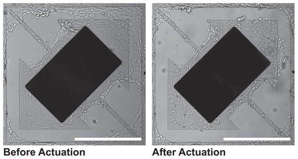
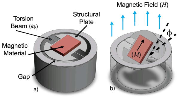
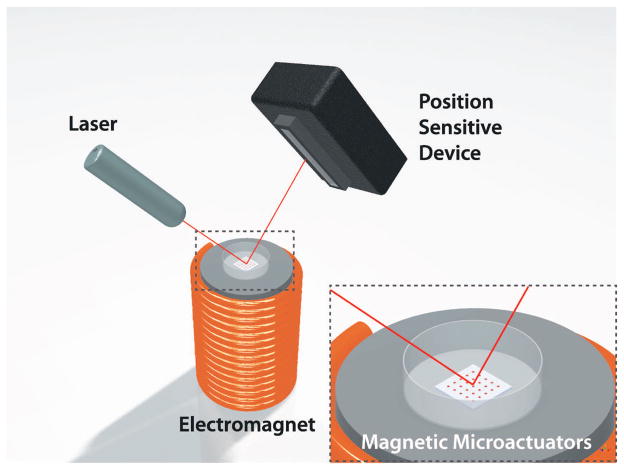
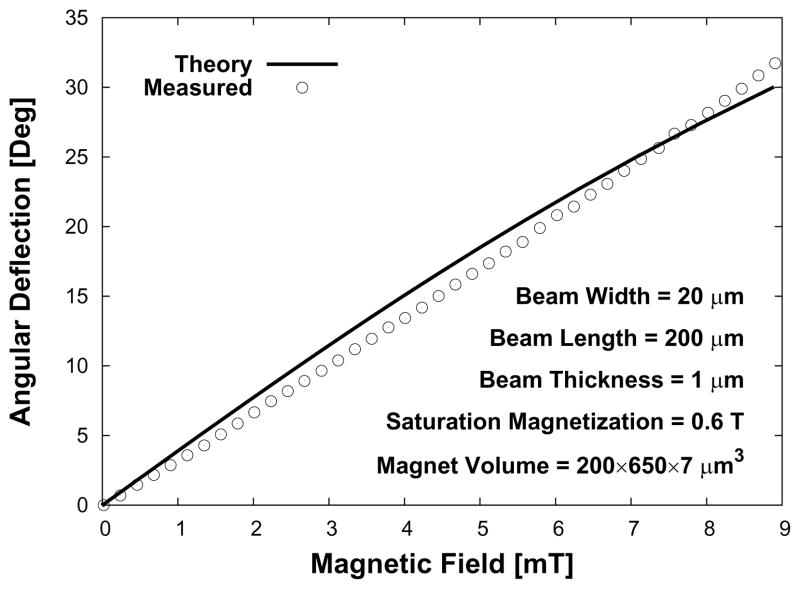
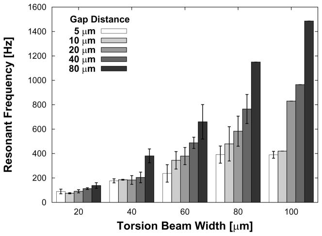
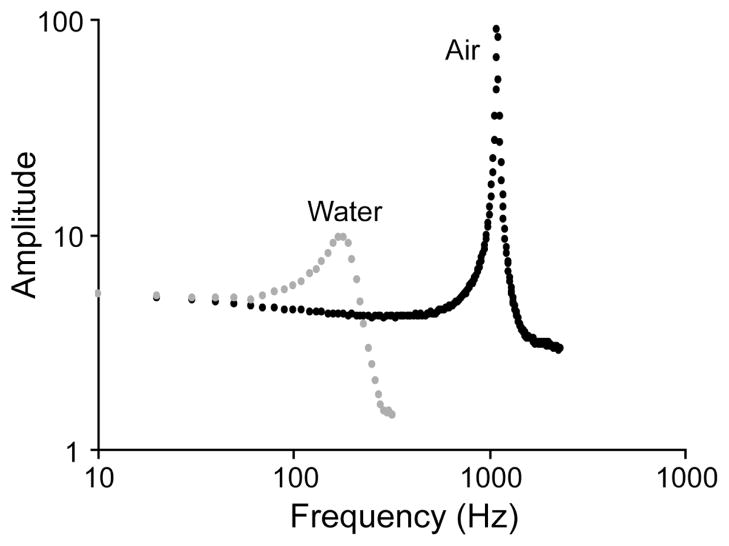
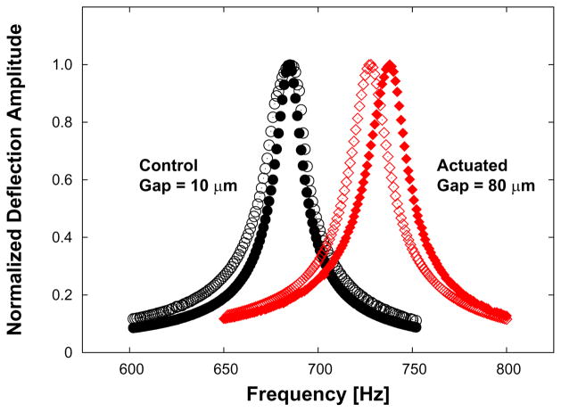
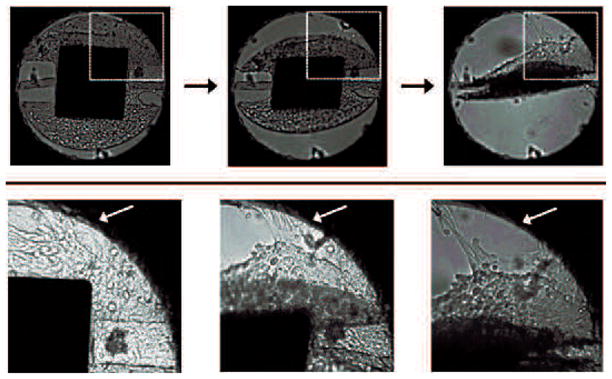
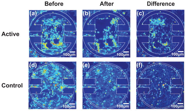
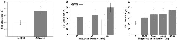
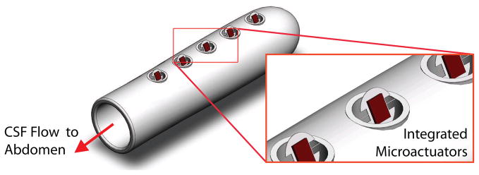
Here we report on the development of torsional magnetic microactuators for displacing biological materials in implantable catheters. Static and dynamic behaviors of the devices were characterized in air and in fluid using optical experimental methods. The devices were capable of achieving large deflections (>60°) and had resonant frequencies that ranged from 70 Hz to 1.5 kHz in fluid. The effect of long-term actuation (>2.5 · 10(8) cycles) was quantified using resonant shift as the metric (Δf < 2%). Cell-clearing capabilities of the devices were evaluated by examining the effect of actuation on a layer of aggressively growing adherent cells. On average, actuated microdevices removed 37.4% of the adherent cell layer grown over the actuator surface. The effect of actuation time, deflection angle, and beam geometry were evaluated. The experimental results indicate that physical removal of adherent cells at the microscale is feasible using magnetic microactuation.


Figures

Figure 1
Figure 1
Illustration of hydrocephalus. (a) the ventricular system of a normal infant and (b) enlarged ventricles and an implanted shunt system. The ventricular catheter directs CSF from the ventricles to the the abdomen via the valve, tubing, and the distal catheter. Adapted from [1].
Figure 2
Figure 2
(Left) Scanning electron micrograph of a fully released (torsion-beam width = 20 μm) device and (Right) an incompletely released non-functional microactuator (torsion-beam width = 80 μm).
Figure 3
Figure 3
Photographs of a portion of the microactuator array with 300×500×7 μm3 magnet volumes and 40-μm torsion beams and a 75-μm-wide gap. Scale bar = 400 μm.
Figure 4
Figure 4
Cell clearing images of second-generation magnetic microactuator with 20-μm-wide torsion beams and a 75-μm-wide gap taken before and after actuation. Note the cellular clearance of cells grown over the gap on the upper right corner. Murine vascular smooth muscle cells (SV40LT-SMC Clone HEP-SA, #CRL-2018, ATCC, Manassas, VA, USA) were used. Scale bar = 400 μm.
Figure 5
Figure 5
3D illustrations of a round magnetic microactuator with torsion-beams: (a) without deflection and (b) under the influence of a magnetic field. The angle of device deflection is indicated by φ.
Figure 6
Figure 6
Above: Top and cross-sectional view of the round torsional magnetic microactuators. Several key design parameters are noted. Below: Three magnet design variations are illustrated.
Figure 7
Figure 7
Microfabrication process of the round DRIE-released third-generation magnetic microactuators.
Figure 8
Figure 8
Digital photograph of a round magnetic microactuator in a deflected state. Schematic top view of device shown in Fig 5. Photograph taken by Jeffrey Tseng.
Figure 9
Figure 9
A 3D illustration of the laser-deflection setup. As the magnetic microactuator rotates at a given applied magnetic field, the position sensitive device captures the displacement of the laser-beam position.
Figure 10
Figure 10
Theoretical and measured deflection and torque for an applied external magnetic field of a sample magnetic microactuators.
Figure 11
Figure 11
Plot of the range of resonant frequencies for all devices with 350×500×7 μm3 magnet volumes. The results are expressed as average ± s.d. See Table 1.
Figure 12
Figure 12
Plot of amplitude as a function of frequency for a device with 20-μm-wide torsion beams and a gap distance of 40 μm in air and also submerged in water. The resonant frequency is shown to be 180 Hz for water and 1.1 kHz for air.
Figure 13
Figure 13
The effect of long-term actuation on resonant frequency. Dynamic responses in air of control (non-actuated) versus actuated devices are shown before (no-fill) and after (filled) actuation. Note the close overlap of frequency response in a sample control device compared to the shifted frequency response in an actuated device. See Table 2. The change in resonance frequency is ~2%.
Figure 14
Figure 14
Images of a round torsional magnetic microactuator with 40-μm-wide torsion beams, 350×400×7 μm3 magnet volume, and a 5-μm-wide gap taken over the course of actuator deflection. The top diagram indicates the portion of the actuator shown in the bottom photograph sequence. Actuation was achieved using a hand-held magnet to facilitate imaging. Note that the cellular layer bridging the gap was torn from the side wall, as indicated by the white arrow.
Figure 15
Figure 15
Images of a round magnetic microactuator with 100-μm-wide torsion beams, 350×500×7 μm3 magnet volume, and a 40-μm-wide gap taken (a) before actuation and (b) after actuating for 30 min at 100 Hz in a magnetic field of 17.8 kA/m. The difference map showing the areas where cells were cleared is shown in (c). Control devices with 60-μm-wide torsion beams and a 5-μm-wide gap were imaged (d) before actuation and (e) after actuating for 30 min at 100 Hz in a magnetic field of 17.8 kA/m. The difference map is shown in (f). Note that actuation of magnetic devices has reduced the overall cellular density, particularly in the top left corner (c) of the actuator.
Figure 16
Figure 16
Effects of various experimental conditions on cellular deflection. Left: comparison between non-actuated control group versus actuated devices. Center: the effect of actuation duration on cell clearance. Right: the cell clearance as a function of deflection magnitude of devices. The clearance data is expressed as average ± s.d.
Figure 17
Figure 17
A 3D illustration of the proposed MEMS-enabled ventricular catheters. Note that the integrated microactuators are shown in actuated state.

Similar articles

Cited by

References

    1. Spina Bifida and Hydrocephalus Association of Nova Scotia. Hydrocephalus Information Page.
    1. Pollack I, Albright A, Adelson P. A randomized, controlled study of a programmable shunt valve versus a conventional valve for patients with hydrocephalus. Neurosurgery. 1999;45:1399–1411. - PubMed
    1. Kestle J, et al. Long-term follow-up date from the shunt design trial. Pediatric Neurosurgery. 2000;33:230–236. - PubMed
    1. Choux M, Di Rocco C, Hockley AD, Walker ML, editors. Pediatric Neurosurgery. Churchill Livingstone; 1999.
    1. National Institute of Neurological Disorders and Stroke. NINDS Hydrocephalus Information Page.

LinkOut - more resources