

Design and Optimization of a 3-Coil Inductive Link for Efficient Wireless Power Transmission
- PMID: 21922034
- PMCID: PMC3171453
- DOI: 10.1109/TBCAS.2011.2158431
Design and Optimization of a 3-Coil Inductive Link for Efficient Wireless Power Transmission
Abstract
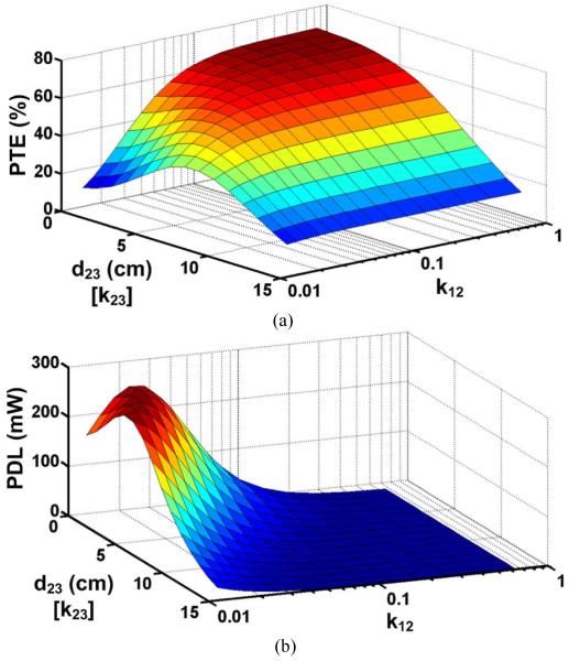
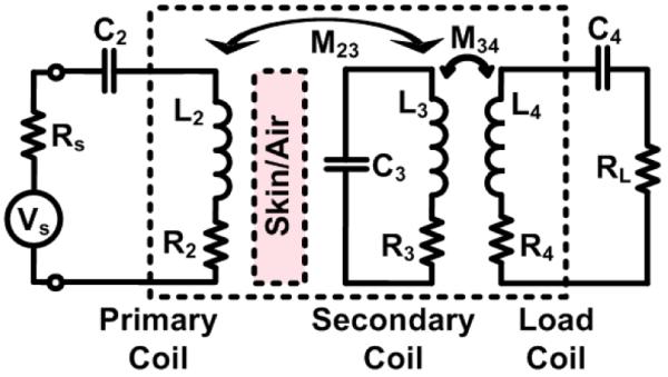
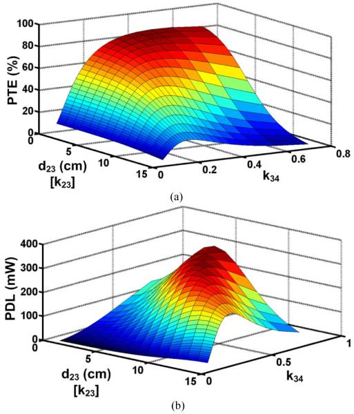
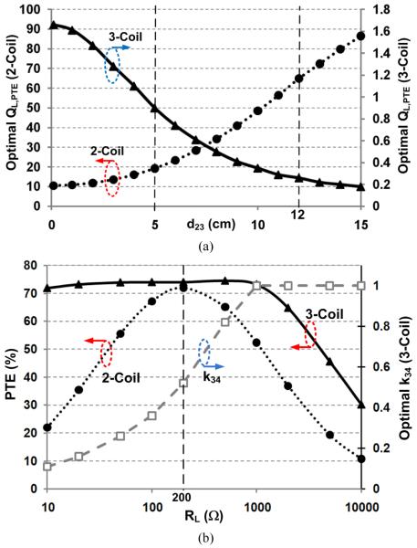
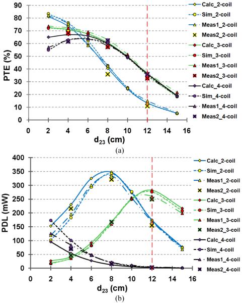
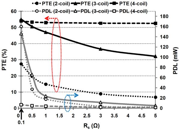
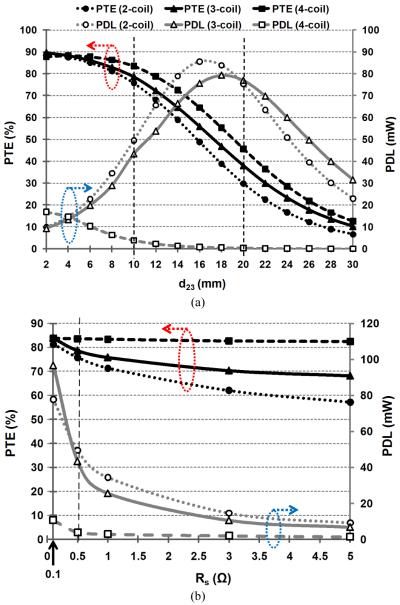
Inductive power transmission is widely used to energize implantable microelectronic devices (IMDs), recharge batteries, and energy harvesters. Power transfer efficiency (PTE) and power delivered to the load (PDL) are two key parameters in wireless links, which affect the energy source specifications, heat dissipation, power transmission range, and interference with other devices. To improve the PTE, a 4-coil inductive link has been recently proposed. Through a comprehensive circuit based analysis that can guide a design and optimization scheme, we have shown that despite achieving high PTE at larger coil separations, the 4-coil inductive links fail to achieve a high PDL. Instead, we have proposed a 3-coil inductive power transfer link with comparable PTE over its 4-coil counterpart at large coupling distances, which can also achieve high PDL. We have also devised an iterative design methodology that provides the optimal coil geometries in a 3-coil inductive power transfer link. Design examples of 2-, 3-, and 4-coil inductive links have been presented, and optimized for 13.56 MHz carrier frequency and 12 cm coupling distance, showing PTEs of 15%, 37%, and 35%, respectively. At this distance, the PDL of the proposed 3-coil inductive link is 1.5 and 59 times higher than its equivalent 2- and 4-coil links, respectively. For short coupling distances, however, 2-coil links remain the optimal choice when a high PDL is required, while 4-coil links are preferred when the driver has large output resistance or small power is needed. These results have been verified through simulations and measurements.
Figures

References
-
- Clark GM. Cochlear Implants: Fundamentals and Applications. Springer-Verlag; New York: 2003.
-
- Chen K, Yang Z, Hoang L, Weiland J, Humayun M, Liu W. An integrated 256-channel epiretinal prosthesis. IEEE J. Solid-State Circuits. 2010 Sep.45(9):1946–1956.
-
- Harrison RR, Watkins PT, Kier RJ, Lovejoy RO, Black DJ, Greger B, Solzbacher F. A low-power integrated circuit for a wireless 100-electrode neural recording system. IEEE J. Solid-State Circuits. 2007 Jan.42(1):123–133.
-
- Hirai J, Kim TW, Kawamura A. Study on intelligent battery charging using inductive transmission of power and information. IEEE Trans. on Power Electronics. 2000 Mar.15(2):335–345.
-
- Finkenzeller K. RFID-Handbook. 2nd ed. Wiley; Hoboken, NJ: 2003.
Grants and funding
LinkOut - more resources
Full Text Sources
Other Literature Sources
