. 2011 Sep;59(9):1927-1937.
doi: 10.1016/j.jmps.2011.04.009.

Periodic cracking of films supported on compliant substrates

Affiliations

Periodic cracking of films supported on compliant substrates

M D Thouless et al. J Mech Phys Solids. 2011 Sep.

Abstract

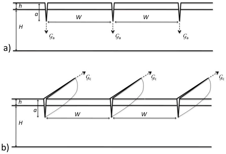
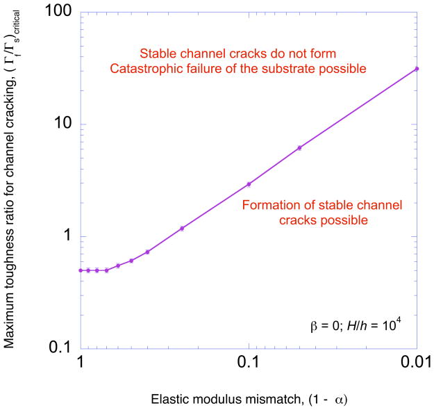
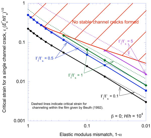
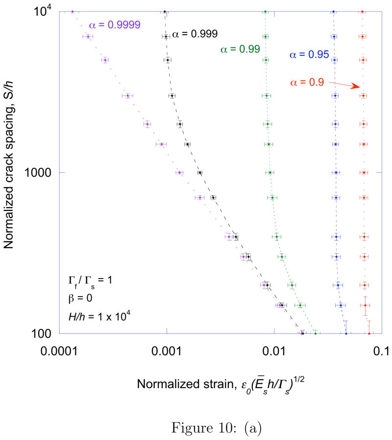
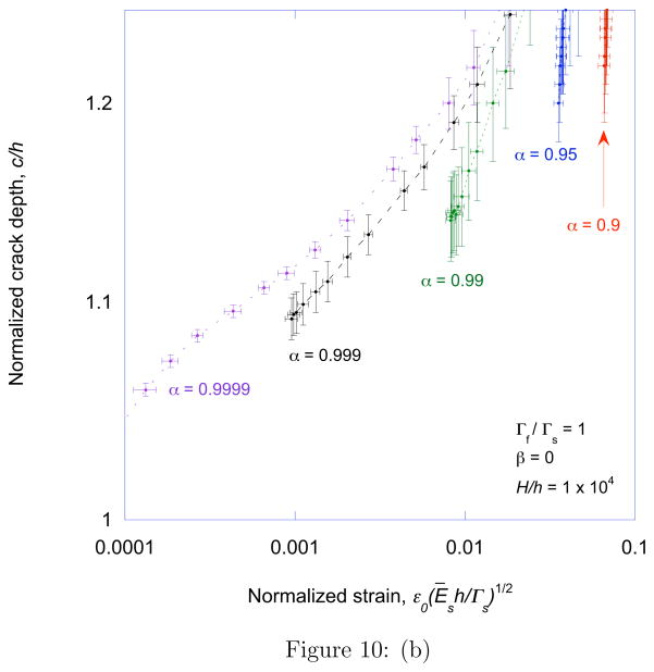
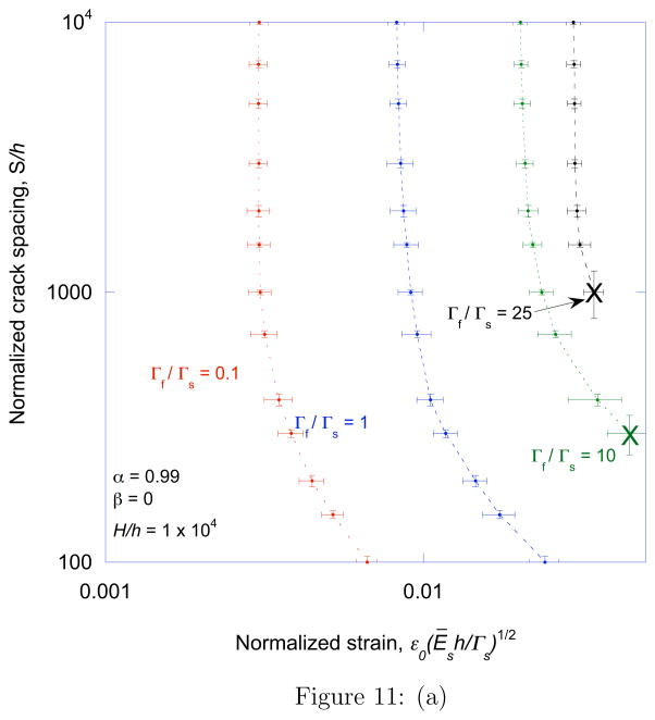
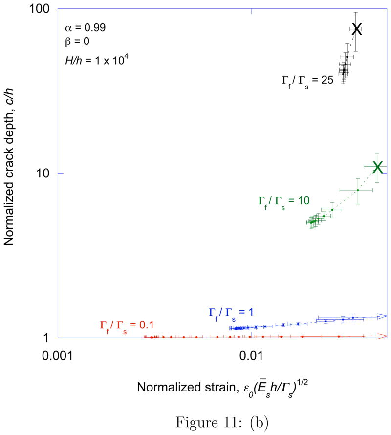
When a tensile strain is applied to a film supported on a compliant substrate, a pattern of parallel cracks can channel through both the film and substrate. A linear-elastic fracture-mechanics model for the phenomenon is presented to extend earlier analyses in which cracking was limited to the film. It is shown how failure of the substrate reduces the critical strain required to initiate fracture of the film. This effect is more pronounced for relatively tough films. However, there is a critical ratio of the film to substrate toughness above which stable cracks do not form in response to an applied load. Instead, catastrophic failure of the substrate occurs simultaneously with the propagation of a single channel crack. This critical toughness ratio increases with the modulus mismatch between the film and substrate, so that periodic crack patterns are more likely to be observed with relatively stiff films. With relatively low values of modulus mismatch, even a film that is more brittle than the substrate can cause catastrophic failure of the substrate. Below the critical toughness ratio, there is a regime in which stable crack arrays can be formed in the film and substrate. The depth of these arrays increases, while the spacing decreases, as the strain is increased. Eventually, the crack array can become deep enough to cause substrate failure.


Figures

Figure 1
Figure 1
The geometry considered in this paper. A stiff film of thickness h and elastic constants Ef and νf is supported on a compliant substrate of thickness H and elastic constants Es and νs. There is a uniform crack array of deptha and spacing W. a) The two-dimesnional geometry, appropriate for cracks propagating perpendicular to the interface and into the substrate. b) The configuration for crack channeling (propagation parallel to the interface).
Figure 2
Figure 2
The energy-release rate tending to drive the cracks of a uniform array into the substrate, formula image
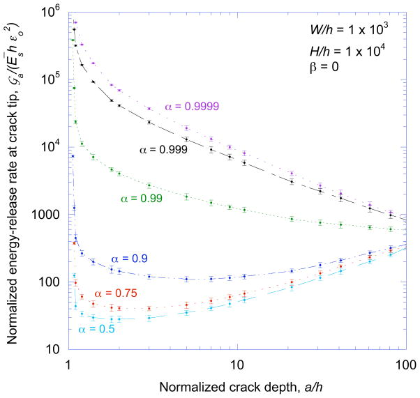
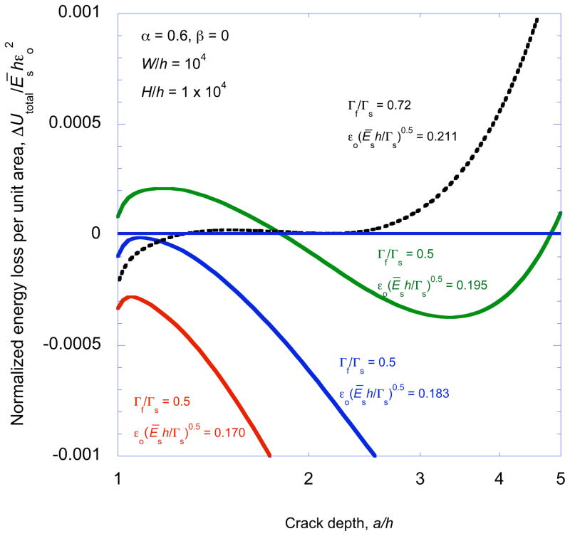
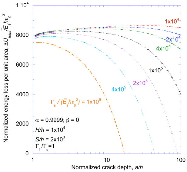
, plotted as a function of crack depth. formula image exhibits both stable and unstable behavior when loaded by a remote tensile strain, if the surface layer has a higher modulus than the substrate.
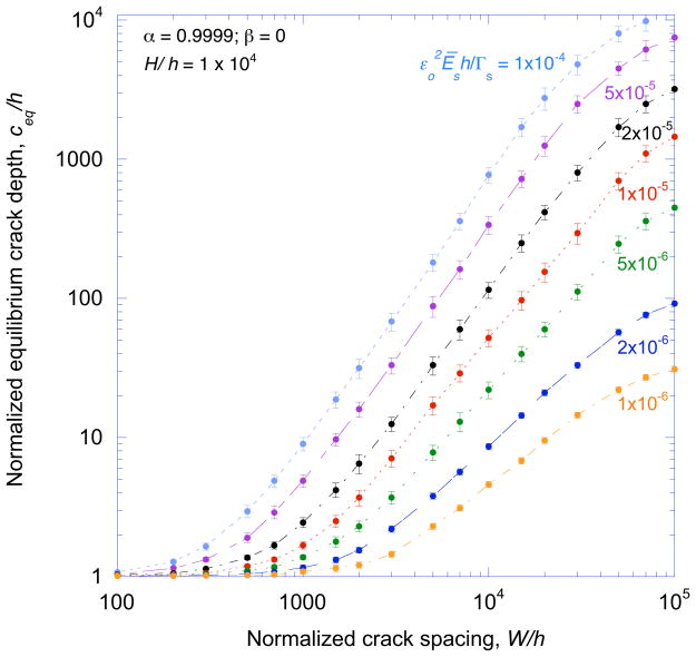
Figure 3
Figure 3
The equilibrium depth for a uniform crack array depends on the applied strain, film thickness, substrate toughness, and crack spacing.
Figure 4
Figure 4
The basic geometries of unit thickness used for the calculations in this paper. The substrate is of thickness H and the film is of thickness h. (a) An uncracked slice of material of width W from which uo(W) is calculated. (b) The same element with a crack of depth a in the middle, from which uc(a, W) is calculated. (c) A crack with an internal pressure, corresponding to the stress field in the uncracked configuration, from which uo(W) − uc(a, W) is calculated directly.
Figure 5
Figure 5
An example of a non-dimensional plot of the total energy loss (per unit area) ΔUtotal/Ēso2 against crack depth a/h for an isolated crack and for different values of normalized strain and toughness ratio.
Figure 6
Figure 6
A non-dimensional plot of the total energy loss (per unit area) ΔUtotal/Ēso2 against crack depth a/h for different values of normalized strain.
Figure 7
Figure 7
A non-dimensional plot of the maximum energy loss (per unit area) ΔUmax/Ēso2 as a function of crack spacing for different values of applied strain.
Figure 8
Figure 8
The critical toughness ratio for the formation of crack arrays plotted as a function of modulus mismatch ratio. Catastrophic failure of the substrate will occur, rather than the propagation of a channel crack, if the toughness of the film relative to the substrate is greater than the critical toughness ratio.
Figure 9
Figure 9
A plot showing how the critical strain required for channeling a single crack across a film and substrate depends on the modulus mismatch ratio. The limit line indicates the maximum strain that can be applied to a coated system without catastrophic failure. Additionally, the results from Beuth [4] are superimposed on this plot.
Figure 10
Figure 10
A plot of the (a) characteristic crack spacing and (b) crack depth as a function of normalized strain, for Γfs = 1 and different values of modulus mismatch. The non-dimensional group H/h has been fixed at 104 for all the calculations in this paper, this is a reasonable approximation for a semi-infinite substrate. However, when α is as high as 0.9999, a ten-fold increase in the substrate thickness increased the crack spacing by about 10%.
Figure 10
Figure 10
A plot of the (a) characteristic crack spacing and (b) crack depth as a function of normalized strain, for Γfs = 1 and different values of modulus mismatch. The non-dimensional group H/h has been fixed at 104 for all the calculations in this paper, this is a reasonable approximation for a semi-infinite substrate. However, when α is as high as 0.9999, a ten-fold increase in the substrate thickness increased the crack spacing by about 10%.
Figure 11
Figure 11
A plot of the (a) characteristic crack spacing and (b) crack depth as a function of normalized strain, for α = 0.99 and different values of the toughness ratio. The “X” on the plots indicates catastrophic failure of the substrate.
Figure 11
Figure 11
A plot of the (a) characteristic crack spacing and (b) crack depth as a function of normalized strain, for α = 0.99 and different values of the toughness ratio. The “X” on the plots indicates catastrophic failure of the substrate.

References

    1. Thouless MD. Crack spacing in brittle films on elastic substrates. Journal of the American Ceramic Society. 1990;73:2144–2146.
    1. Thouless MD, Olsson E, Gupta A. Cracking of brittle films on elastic substrates. Acta Metallurgica et Materialia. 1992;40:1287–1292.
    1. Hutchinson JW, Suo Z. Mixed mode cracking in layered materials. Advances in Applied Mechanics. 1992;29:63–191.
    1. Beuth JL., Jr Cracking of thin films bonded in residual tension. International Journal of Solids and Structures. 1992;29:1657–1675.
    1. Shenoy VB, Schwartzman AF, Freund LB. Crack patterns in brittle thin films. International Journal of Fracture. 2000;103:1–17.

LinkOut - more resources