. 2011 Sep;16(9):096020.
doi: 10.1117/1.3630115.

Simultaneous optical mapping of transmembrane potential and wall motion in isolated, perfused whole hearts

Affiliations

Simultaneous optical mapping of transmembrane potential and wall motion in isolated, perfused whole hearts

Elliot B Bourgeois et al. J Biomed Opt. 2011 Sep.

Abstract

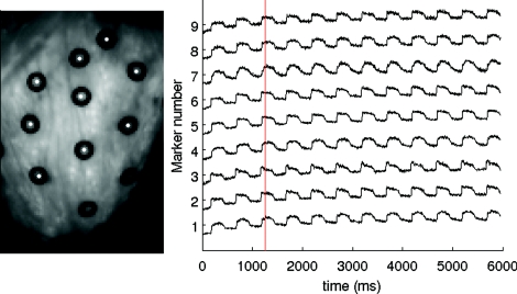
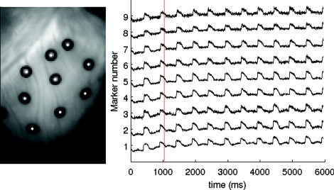
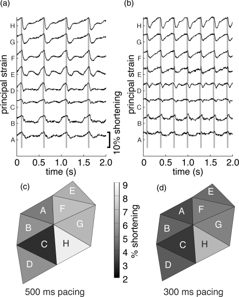
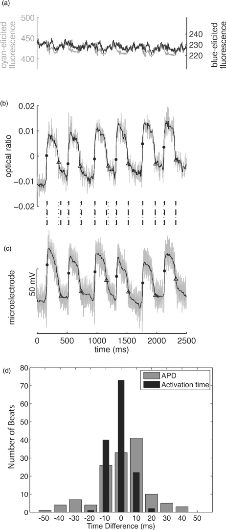
Optical mapping of cardiac propagation has traditionally been hampered by motion artifact, chiefly due to changes in photodetector-to-tissue registration as the heart moves. We have developed an optical mapping technique to simultaneously record electrical waves and mechanical contraction in isolated hearts. This allows removal of motion artifact from transmembrane potential (V(m)) recordings without the use of electromechanical uncoupling agents and allows the interplay of electrical and mechanical events to be studied at the whole organ level. Hearts are stained with the voltage-sensitive dye di-4-ANEPPS and ring-shaped markers are attached to the epicardium. Fluorescence, elicited on alternate frames by 450 and 505 nm light-emitting diodes, is recorded at 700 frames∕ per second by a camera fitted with a 605 ± 25 nm emission filter. Marker positions are tracked in software. A signal, consisting of the temporally interlaced 450 and 505 nm fluorescence, is collected from the pixels enclosed by each moving ring. After deinterlacing, the 505 nm signal consists of V(m) with motion artifact, while the 450 nm signal is minimally voltage-sensitive and contains primarily artifacts. The ratio of the two signals estimates V(m). Deformation of the tissue enclosed by each set of 3 rings is quantified using homogeneous finite strain.


Figures

Video 1
Video 1
Optical mapping of 500 ms pacing in a beating heart. Vm traces are shown for the 9 numbered markers in Fig. 3b. A vertical red line shows the current video position in time. White dots indicate depolarization and repolarization of the tissue encircled by each marker. Frame rate is 1/10 real time. Only cyan frames are shown. Activation wavefronts are visible as slightly darker shadows propagating across the heart. (MPEG, 9.3 MB) .
Video 2
Video 2
500 ms pacing in a BDM-treated swinging heart. Video layout is the same as in . (MPEG, 9.3 MB).
Figure 1
Figure 1
Excitation light synchronization. Initially, both cyan and royal blue on-intensity is set to 0. When blue on-intensity is turned up (arrow), light collected during cyan frames (black dots) remains at baseline, while light collected during alternating blue frames (gray circles) is elevated.
Figure 2
Figure 2
Binary mask creation for tracking an epicardial marker through frames of video. (a) Original subimage of one marker. (b) 4× resampling of image in (a) (bicubic interpolation). (c) Edges of image in (b) detected with Canny edge detection. (d) Morphological dilation closes any gaps in the inner and outer edges of the marker. (e) A flood-fill operation is applied to the center of the image in (d). The area identified by flood-fill is then dilated to compensate for the dilation performed in (d). (f) Subtraction of a dilation of the image in (e) from the image in (d) yields a dilated edge image with the inner ring removed. (g) Flood-fill identifies the outer edge of the marker. The area identified by flood-fill is then dilated to compensate for the dilation performed in (d). (h) Subtraction of the image in (e) from the image in (g) gives a binary mask of the marker. (i) The mask binary mask in (g) is resampled to the image resolution used for motion tracking (8× original camera resolution). The white lines show the inner and outer contours of the resampled binary marker mask, overlaid on an 8× resampling of the original sub-image.
Figure 3
Figure 3
Ventricular markers. (a) Heart with 14 markers attached with cyanoacrylate adhesive gel. (b) One frame of CCD camera video. Local Vm signals are obtained from the fluorescence emitted from inside each marker. Marker numbers correspond to action potential traces in Fig. 5. (c) Triples of markers define regions for strain measurements. Triangles, lettered A–H, correspond to major axis strain plots in Fig. 7.
Figure 4
Figure 4
Excitation ratiometry. (a) Time-interlaced fluorescence signal obtained from a single marker tracked through frames of CCD video. Signal is from marker number 5 in Fig. 3b during 700 ms bipolar pacing. (b) De-interlaced signals, corresponding to alternating frames of cyan and royal blue excitation. (c) Common artifacts in the two fluorescence signals (primarily motion) are attenuated in the ratio signal. Fluorescence units are analog-to-digital conversion counts. No temporal filtering was applied to these signals.
Figure 5
Figure 5
(a)–(c) Fluorescent action potential signals obtained from all numbered markers in Fig. 3b during 500 ms bipolar pacing for (a) beating, (b) BDM-treated stationary, and (c) BDM-treated swinging heart recordings. (d)–(f) Relative marker displacement during the mapping runs in (a)–(c). Displacement was computed as the distance from the marker to the origin of a 20 × 20 pixel region containing the marker. (g)–(I) Fluorescent action potential signals obtained from the same numbered markers during 300 ms bipolar pacing for (g) beating, (h) BDM-treated stationary, and (i) BDM-treated swinging heart recordings. J-L(j)–(l) Relative marker displacement during the mapping runs in (g)–(i). Displacements are computed in the same manner as for (d)–(f). The calibration bar in (d) applies to all displacement traces. No temporal filtering was applied to these signals. (The recordings of 500 ms pacing in beating and BDM-treated swinging conditions are also shown in Videos 1 and 2, respectively.)
Figure 6
Figure 6
Action potential durations. (a) APD in beating and BDM-treated (stationary) recordings. At each pacing rate, APDs for all markers are averaged to give a single APD value for each recording. Measurements that are common to a single heart are connected by lines. Error bars show standard deviations. APDs differed significantly for beating and BDM recordings at each pacing rate. (b) APD in stationary and swinging BDM-treated heart recordings. APDs for corresponding hearts are paired. APD values did not differ significantly between stationary and swinging conditions.
Figure 7
Figure 7
(a) and (b) Maximum principal finite strain measured in the camera's view plane for each triangle (A–H) shown in Fig. 3c. Gray bars indicate time of end-diastole, identified by the average activation time for the three vertices of each triangle. The calibration bar applies to all traces. (a) 500 ms pacing. (b) 300 ms pacing. Spatial distributions of peak shortening for 500 ms (c) and 300 ms (d) pacing.
Figure 8
Figure 8
Simultaneous optical and floating microelectrode data. (a) shows the individual cyan- and blue-elicited optical signals recorded from a single epicardial marker during 400 ms pacing. (b) is the corresponding ratio signal and (c) is the simultaneously recorded microelectrode signal. The signals in (b) and (c) are filtered by 5-point smoothing followed by 11-point median filtering. Unfiltered signals are gray and filtered signals are black. Dots and triangles indicate depolarization and repolarization times, respectively. Vertical lines between (b) and (c) show the relative timing of depolarization/repolarization events in the two signals (dotted lines correspond to the optical signal, dashed lines correspond to the electrical signal). (d) Shows histograms of the differences in activation time (black) and APD (gray) between optical and electrical signals for all recorded beats. Bins are 10 ms wide.
Figure 9
Figure 9
Illumination profile across one row of pixels during cyan (gray line) and royal blue (thin black line) illumination of a flat paper target. Royal blue illumination is more uniform.

Similar articles

Cited by

References

    1. Shenasa M., Hendricks G., Borggrefe B., and Breithardt G., Cardiac Mapping. 3rd Ed., Blackwell Publishing, Oxford, United Kingdom: (2009).
    1. Efimov I. R., Nikolski V. P., and Salama G., “Optical imaging of the heart,” Circ. Res. 95, 21–33 (2004).10.1161/01.RES.0000130529.18016.35 - DOI - PubMed
    1. Fedorov V., Lozinsky I., Sosunov E., Anyukhovsky E., Rosen M., Balke C., and Efimov I. R., “Application of blebbistatin as an excitation-contraction uncoupler for electrophysiologic study of rat and rabbit hearts,” Heart Rhythm 4, 619–626 (2007).10.1016/j.hrthm.2006.12.047 - DOI - PubMed
    1. Qin H., Kay M. W., Chattipakorn N., Redden D. T., Ideker R. E., and Rogers J. M., “Effects of heart isolation, voltage-sensitive dye, and electromechanical uncoupling agents on ventricular fibrillation,” Am. J. Physiol. Heart Circ. Physiol. 284, H1818–H1826 (2003).10.1152/ajpheart.00923.2002 - DOI - PubMed
    1. Schiller N. B., Shah P. M., Crawford M., DeMaria A., Devereux R., Feigenbaum H., Gutgesell H., Reichek N., Sahn D., Schnittger I., Silverman N. H., and Tajik A. J., “Recommendations for quantitation of the left ventricle by two-dimensional echocardiography. American Society of Echocardiography Committee on Standards, Subcommittee on Quantitation of Two-Dimensional Echocardiograms,” J. Am. Soc. Echocardiogr. 2, 358–367 (1989). - PubMed

Publication types