

Specific issues in small animal dosimetry and irradiator calibration
- PMID: 21961967
- PMCID: PMC3646294
- DOI: 10.3109/09553002.2011.556178
Specific issues in small animal dosimetry and irradiator calibration
Abstract
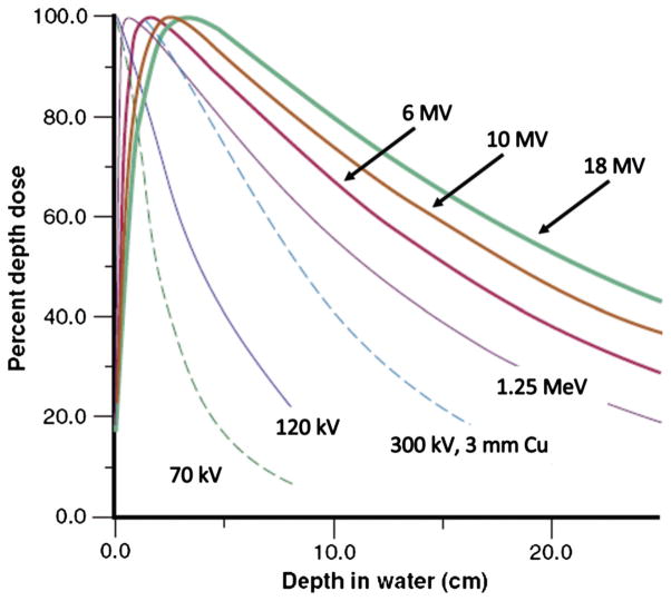
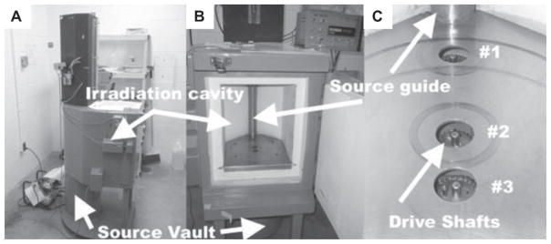
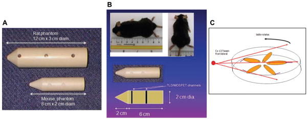
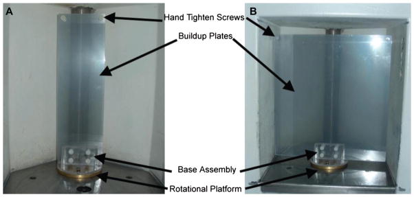
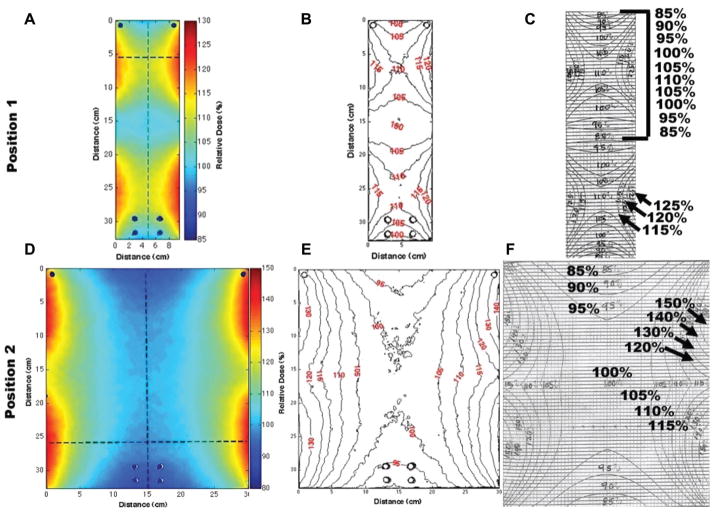
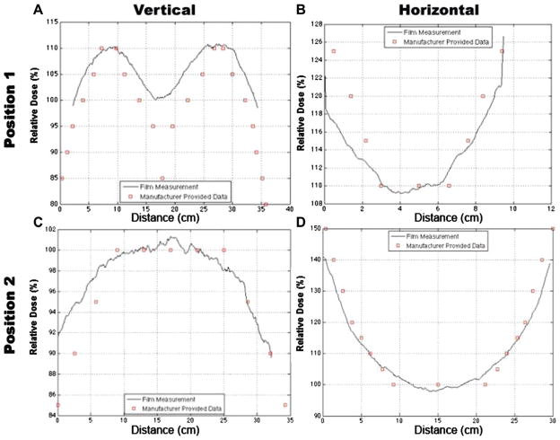
Purpose: In response to the increased risk of radiological terrorist attack, a network of Centers for Medical Countermeasures against Radiation (CMCR) has been established in the United States, focusing on evaluating animal model responses to uniform, relatively homogenous whole- or partial-body radiation exposures at relatively high dose rates. The success of such studies is dependent not only on robust animal models but on accurate and reproducible dosimetry within and across CMCR. To address this issue, the Education and Training Core of the Duke University School of Medicine CMCR organised a one-day workshop on small animal dosimetry. Topics included accuracy in animal dosimetry accuracy, characteristics and differences of cesium-137 and X-ray irradiators, methods for dose measurement, and design of experimental irradiation geometries for uniform dose distributions. This paper summarises the information presented and discussed.
Conclusions: Without ensuring accurate and reproducible dosimetry the development and assessment of the efficacy of putative countermeasures will not prove successful. Radiation physics support is needed, but is often the weakest link in the small animal dosimetry chain. We recommend: (i) A user training program for new irradiator users, (ii) subsequent training updates, and (iii) the establishment of a national small animal dosimetry center for all CMCR members.
Conflict of interest statement
The authors report no conflicts of interest. The authors alone are responsible for the content and writing of the paper.
Figures
References
-
- Berman AT, Rengan R. New approaches to radiotherapy as definitive treatment for inoperable lung cancer. Seminars in Thoracic and Cardiovascular Surgery. 2008;20:188– 197. - PubMed
-
- Blatt DR, Friedman WA, Bova FJ, Theele DP, Mickle JP. Temporal characteristics of radiosurgical lesions in an animal model. Journal of Neurosurgery. 1994;80:1046– 1055. - PubMed
-
- Bourland JD. Radiation oncology physics. In: Gunderson LL, Tepper JE, editors. Clinical radiation oncology. 2. Philadelphia, PA: WB Saunders Company; 2006.
-
- Bourland JD. Image-guided radiation treatment. In: Wolbarst AB, Mossman KL, Hendee WR, editors. Advances in medical physics. Madison, WI: Medical Physics Publishing; 2008.
Publication types
MeSH terms
Substances
Grants and funding
LinkOut - more resources
Full Text Sources