

How do CAD models compare with reverse engineered manufactured components for use in wear analysis?
- PMID: 22016002
- PMCID: PMC3369103
- DOI: 10.1007/s11999-011-2143-0
How do CAD models compare with reverse engineered manufactured components for use in wear analysis?
Abstract
Background: To accurately quantify polyethylene wear in retrieved arthroplasty components, the original geometry of the component must be estimated accurately using a reference geometry such as a computer-aided design (CAD) model or a never-implanted insert. However, differences may exist between the CAD model and manufactured inserts resulting from manufacturing tolerances.
Questions/purposes: We quantified the deviations between CAD models and newly manufactured inserts and determined how these deviations compared with using a never-implanted insert as a reference geometry.
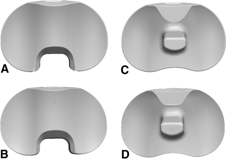
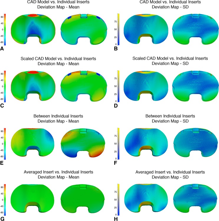
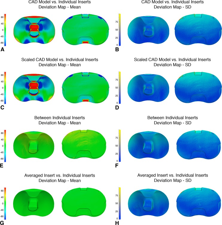
Methods: We obtained five cruciate-retaining (CR) and five posterior-stabilizing (PS) tibial inserts and their CAD models. The inserts were scanned and reconstructed using microcomputed tomography (micro-CT). Differences in volume and surface geometry were measured among (1) the individual inserts; (2) between the inserts and a CAD model; and (3) between the inserts and a reference geometry constructed from multiple scanned inserts averaged together.
Results: The micro-CT volumes were, on average, 0.4% smaller (34-178 mm(3)) than the CAD model volumes. The mean deviation between the CAD model and insert surface geometry was 25.7 μm smaller for CR and 36.8 μm smaller for PS. The mean deviation between the inserts and an averaged reference geometry was 1.4 μm larger for CR and 0.4 μm smaller for PS.
Conclusions: Deviations exist between manufactured tibial inserts and CAD models that could cause errors in wear measurements. Scanned inserts may better represent the preimplantation geometry of worn inserts than CAD models, depending on the manufacturing variability between lots.
Clinical relevance: The magnitude of the error in estimation of the preimplantation geometry of a retrieved component could add or subtract the equivalent of 1 year of wear.
Figures
Similar articles
-
In vitro quantification of wear in tibial inserts using microcomputed tomography.Clin Orthop Relat Res. 2011 Jan;469(1):107-12. doi: 10.1007/s11999-010-1490-6. Clin Orthop Relat Res. 2011. PMID: 20676810 Free PMC article.
-
Can microcomputed tomography measure retrieved polyethylene wear? Comparing fixed-bearing and rotating-platform knees.Clin Orthop Relat Res. 2013 Jan;471(1):86-93. doi: 10.1007/s11999-012-2513-2. Clin Orthop Relat Res. 2013. PMID: 22879092 Free PMC article.
-
Manufacturing lot affects polyethylene tibial insert volume, thickness, and surface geometry.Proc Inst Mech Eng H. 2013 Aug;227(8):884-9. doi: 10.1177/0954411913486755. Epub 2013 Apr 26. Proc Inst Mech Eng H. 2013. PMID: 23636769
-
Posterior-stabilized inserts are preferable to cruciate-substituting ultracongruent inserts due to more favourable kinematics and stability.Knee Surg Sports Traumatol Arthrosc. 2018 Nov;26(11):3300-3310. doi: 10.1007/s00167-018-4872-z. Epub 2018 Feb 19. Knee Surg Sports Traumatol Arthrosc. 2018. PMID: 29459998
-
A Review of Image-Based Simulation Applications in High-Value Manufacturing.Arch Comput Methods Eng. 2023;30(3):1495-1552. doi: 10.1007/s11831-022-09836-2. Epub 2023 Jan 18. Arch Comput Methods Eng. 2023. PMID: 36685137 Free PMC article. Review.
Cited by
-
Radiostereometric Analysis Permits In Vivo Measurement of Very Small Levels of Wear in TKA.Clin Orthop Relat Res. 2019 Jan;477(1):80-90. doi: 10.1097/CORR.0000000000000399. Clin Orthop Relat Res. 2019. PMID: 30794231 Free PMC article.
-
Current Total Knee Designs: Does Baseplate Roughness or Locking Mechanism Design Affect Polyethylene Backside Wear?Clin Orthop Relat Res. 2017 Dec;475(12):2970-2980. doi: 10.1007/s11999-017-5494-3. Epub 2017 Sep 13. Clin Orthop Relat Res. 2017. PMID: 28905208 Free PMC article.
-
Attenuation correction for PET/MRI to measure tracer activity surrounding total knee arthroplasty.Eur J Hybrid Imaging. 2022 Nov 7;6(1):31. doi: 10.1186/s41824-022-00152-3. Eur J Hybrid Imaging. 2022. PMID: 36336748 Free PMC article.
References
-
- Blunt L, Bills P, Jiang X, Chakrabarty G. Improvement in the assessment of wear of total knee replacements using coordinate-measuring machine techniques. Proc Inst Mech Eng H. 2008;222:309–318. - PubMed
-
- Conditt MA, Stein JA, Noble PC. Factors affecting the severity of backside wear of modular tibial inserts. J Bone Joint Surg Am. 2004;86:305–311. - PubMed
Publication types
MeSH terms
Substances
LinkOut - more resources
Full Text Sources
Medical
Miscellaneous
