. 2012 Jan 1;302(1):H287-98.
doi: 10.1152/ajpheart.00824.2011. Epub 2011 Oct 21.

Visualization and quantification of whole rat heart laminar structure using high-spatial resolution contrast-enhanced MRI

Affiliations

Visualization and quantification of whole rat heart laminar structure using high-spatial resolution contrast-enhanced MRI

Stephen H Gilbert et al. Am J Physiol Heart Circ Physiol. .

Abstract

It has been shown by histology that cardiac myocytes are organized into laminae and this structure is important in function, both influencing the spread of electrical activation and enabling myocardial thickening in systole by laminar sliding. We have carried out high-spatial resolution three-dimensional MRI of the ventricular myolaminae of the entire volume of the isolated rat heart after contrast perfusion [dimeglumine gadopentate (Gd-DTPA)]. Four ex vivo rat hearts were perfused with Gd-DTPA and fixative and high-spatial resolution MRI was performed on a 9.4T MRI system. After MRI, cryosectioning followed by histology was performed. Images from MRI and histology were aligned, described, and quantitatively compared. In the three-dimensional MR images we directly show the presence of laminae and demonstrate that these are highly branching and are absent from much of the subepicardium. We visualized these MRI volumes to demonstrate laminar architecture and quantitatively demonstrated that the structural features observed are similar to those imaged in histology. We showed qualitatively and quantitatively that laminar architecture is similar in the four hearts. MRI can be used to image the laminar architecture of ex vivo hearts in three dimensions, and the images produced are qualitatively and quantitatively comparable with histology. We have demonstrated in the rat that: 1) laminar architecture is consistent between hearts; 2) myolaminae are absent from much of the subepicardium; and 3) although localized orthotropy is present throughout the myocardium, tracked myolaminae are branching structures and do not have a discrete identity.


Figures

Fig. 1.
Fig. 1.
A: light microscope image (digital microscope, Dino-Lite AM-2011; AnMo, Taiwan) of a transmural cut through an unfixed rat heart. Myolaminae are clearly seen as bright thin stripes as opposed to darker cleavage planes. B: cardiac location of the image in A. A movie from which the still image in A was obtained is available in Supplemental Material. In this movie the slide of the myolaminae accompanying myocardial contraction is seen and demonstrates that laminar structure is readily observed in the unloaded ventricular wall. RV, right ventricle.
Fig. 2.
Fig. 2.
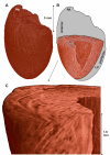
Three-dimensional visualization of myolaminar architecture from a rat heart (MRI dataset C1LR, 50 × 50 × 50 μm). In the MRI images, in contrast with Fig. 1, the cleavage planes appear brighter than the myolaminae. The atria have been removed by manual segmentation. A: exterior of heart, left/lateral view. PA, root of pulmonary artery/infundibulum of the right ventricle. B: the same view of the ventricles as in A, with the lateral left ventricle (LV) wall and heart base cropped. The 3-dimensional branching network of the myolaminae can be seen on the short- and long-axis cut surfaces. (myolaminae: red; cleavage planes: white). C: magnified view of the anterior myocardium from B (region in box). Greater detail of 3-dimensional myolaminar branching can be seen.
Fig. 3.
Fig. 3.
Laminar architecture in a near-equatorial short-axis slice (MRI dataset C1HR, resolution of 25 × 25 × 37 μm). Sub-epi, subepicardial myocardium; mid, midmyocardium; sub-endo, subendocardial myocardium. In the MRI images, in contrast with Fig. 1, the cleavage planes appear brighter than the myolaminae. A: short-axis slice. B: magnified region of short-axis slice. A movie of the progression through the MRI short-axis stack from apex to base (associated with this figure) is available in the Supplementary Material. In the movie the 3-dimensional continuity of laminar structure is clearly seen, with the more loose laminar structure in the subendocardium, becoming more compact toward the subepicardium. Laminar structure is seen to be absent closest to the epicardium. The myolaminar structure in the short-axis slices can be seen to correspond to the structure in the cut transmural surface of the perfused rat heart in Fig. 1.
Fig. 4.
Fig. 4.
Validation of MRI determined laminar organization (C1HR, 25 × 25 × 39 μm) against histology from the same heart. Selected near coronal histology sections were registered against the corresponding cross section of the MRI from the same heart and the LV isolated by image segmentation. A: for slice 1, the registered MRI and histology images are shown at left. A, middle: image local orientation, which is measured from the image horizontal axis and colored according to the color scale shown. A, right: difference in orientation angle between MRI and histology. B: similarly, for slice 2, images of the MRI, histology, orientation, and difference in orientation are shown. Note that the demarcated red center of the MRI orientation image for slice 2 is due to the angles transitioning from −90° to +90° (blue to red), a consequence of the noncircular color scale. C: cardiac location of the near coronal slice 1 and slice 2. LAA, left atrial appendage; PA, pulmonary artery root.
Fig. 5.
Fig. 5.
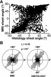
Correlation and statistical distributions of MRI and histological laminar orientation measurements. A: correlation plot of pooled histology versus pooled C1HR MRI in-plane sheet angle for the 3 selected slices (2 of which are shown in Fig. 4). B: rose diagram for pooled in-plane sheet angles from MRI and histology from the 3 selected slices. The circular correlation coefficient r0 = 0.35 with P < 10−5 is shown.
Fig. 6.
Fig. 6.
Quantification of transmural in-plane sheet angle in selected transmural profiles in slice 1 and slice 2 obtained from MRI (C1HR and histology). A: C1HR MRI slice 1 (as in Fig. 4) with short-axis transmural profiles i–iii. The transmural profiles are marked on the corresponding histology image and angle difference map. A, right: transmural profiles for i–iii with corresponding r0 and P values. B: C1HR MRI slice 2 (as in Fig. 4) with short-axis transmural profiles iv–vi. The transmural profiles are marked on the corresponding histology image and angle difference map. B, right: transmural profiles for iv–vi with corresponding r0 and P values. LVFW, left ventricular free wall; VC, ventricular cavity; IVS, interventricular septum.
Fig. 7.
Fig. 7.
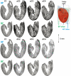
Comparison of in-plane sheet orientation in affine and deformably registered MR images. Top 2 rows: long-axis sections through the 50 × 50 × 50 μm images of 4 hearts after vertical alignment of the long-axis of C1 and affine registration of the other 3 hearts (C1LR and aC2LR-aC4LR). Bottom 2 rows: long-axis sections through the 50 × 50 × 50 μm images of 4 hearts after vertical alignment of the long-axis of C1 and deformable registration of the other 3 hearts (C1LR and dC2LR-dC4LR). The cardiac location of the slices (labeled 45° and 90°) are shown at right, where the atria have been removed by manual segmentation. The laminar structure is clearly visible in all hearts, although it is less defined than in the 25 × 25 × 37 μm image of C1 in Figs. 3 and 4. The laminar architecture has the same overall features, and these can be seen to be aligned.
Fig. 8.
Fig. 8.
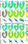
Quantitative comparison of in-plane sheet angle between deformably registered MR images (C1LR and dC2LR-dC4LR). The selected long-axis slices are those described in Fig. 7. A: orientation (top row) maps for a selected near coronal long-axis slice (45°→) for the 4 hearts. Below this (second row) are the corresponding angular differences with comparison to C1LR. The r0 and P values for each pair-wise correlation to C1LR are shown. In the bottom row are the rose diagrams of the in-plane sheet angle distributions. B is laid out as in A, with a second selected long-axis slice (90°→).
Fig. 9.
Fig. 9.
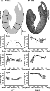
Transmural profiles for MRI slice 45° of the 4 hearts (the selected slice is the same as described in Fig. 7). A: location of the selected left and right basal, equatorial and apical transmural radii. B: laminar structure in the selected slice (C1LR). Transmural angle profiles from the base, equator, and apex of the left ventricular free wall and of the base, equator, apex of the right ventricular free wall are shown. In this figure angles are referenced to the epicardial tangent. Angles are reported with respect to these transmural radii, and the positive in-plane sheets are defined as those that rise toward the cardiac base from the LV centroid.
Fig. 10.
Fig. 10.
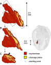
The 3-dimensional structure of adjacent myolaminae. Cleavage planes and myolaminae were manually tracked within C1HR starting from point (*), and the resultant structure was visualized. From the starting point the most obvious 3-dimensional continuation of the laminae was followed. At many points throughout the tracking there were equally favorable paths (as indicated by the arrow head on C). A 3-dimensionally branching orthotropic structure therefore results, as can be seen in A and the cut-away images B and C. Both the myolaminae and the cleavage planes branch in this manner, being structurally complementary to each other. Note that the branching of the myolaminae continues in 3 dimensions and the boundaries of the structure shown are for illustrative purposes.

References

    1. Abramoff MD, Magelhaes PJ, Ram SJ. Image processing with ImageJ. Biophotonics International 11: 36–42, 2004
    1. Anderson RH, Smerup M, Sanchez-Quintana D, Loukas M, Lunkenheimer PP. The three-dimensional arrangement of the myocytes in the ventricular walls. Clin Anat 22: 64–76, 2009 - PubMed
    1. Arts T, Costa KD, Covell JW, McCulloch AD. Relating myocardial laminar architecture to shear strain and muscle fiber orientation. Am J Physiol Heart Circ Physiol 280: H2222–H2229, 2001 - PubMed
    1. Berens P. CircStat: a MATLAB Toolbox for Circular Statistics. Journal of Statistical Software 31: 1–21, 2009
    1. Bishop MJ, Plank G, Burton RA, Schneider JE, Gavaghan DJ, Grau V, Kohl P. Development of an anatomically detailed MRI-derived rabbit ventricular model and assessment of its impact on simulations of electrophysiological function. Am J Physiol Heart Circ Physiol 298: H699–H718, 2010 - PMC - PubMed

Publication types