. 2011 Dec 21;11(24):4165-73.
doi: 10.1039/c1lc20557a. Epub 2011 Nov 10.

Ensembles of engineered cardiac tissues for physiological and pharmacological study: heart on a chip

Affiliations

Ensembles of engineered cardiac tissues for physiological and pharmacological study: heart on a chip

Anna Grosberg et al. Lab Chip. .

Abstract

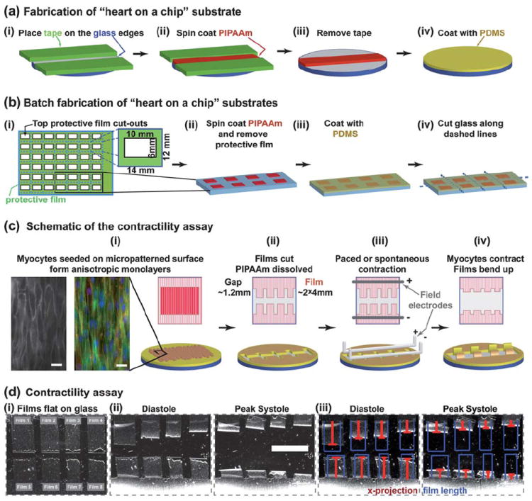
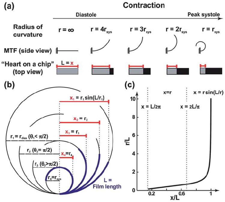
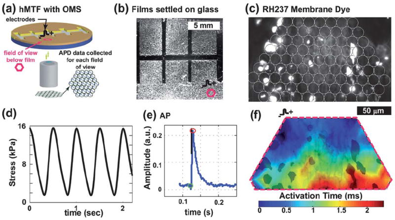
Traditionally, muscle physiology experiments require multiple tissue samples to obtain morphometric, electrophysiological, and contractility data. Furthermore, these experiments are commonly completed one at a time on cover slips of single cells, isotropic monolayers, or in isolated muscle strips. In all of these cases, variability of the samples hinders quantitative comparisons among experimental groups. Here, we report the design of a "heart on a chip" that exploits muscular thin film technology--biohybrid constructs of an engineered, anisotropic ventricular myocardium on an elastomeric thin film--to measure contractility, combined with a quantification of action potential propagation, and cytoskeletal architecture in multiple tissues in the same experiment. We report techniques for real-time data collection and analysis during pharmacological intervention. The chip is an efficient means of measuring structure-function relationships in constructs that replicate the hierarchical tissue architectures of laminar cardiac muscle.


Figures

Fig. 1
Fig. 1
“Heart on a chip” assembly and use. (a) Fabrication of 25 mm round substrates; (b) schematic representation of batch fabrication of substrates with large glass sections for higher throughput; (c) contractility assay is run using anisotropic layers of myocytes; bottom row shows a 3D schematic representation, top row shows the view from above; the insets in (i): RH237 membrane dye stain (left) and an immunostain of α-actinin – red, actin – green, nuclei – blue (right), scale bar 20 μm; (d) Contractility experiment (PDMS layer = 18.6 μm): (i) Brightfield images of films attached to the substrate, (ii) films bend up at diastole and peak systole, and (iii) the length of films (blue) and x-projection (red) overlaid on “heart on a chip” images – scale bar 5 mm.
Fig. 2
Fig. 2
Calculation of the radius of curvature. (a) A schematic drawing contrasting the view of the regular MTF assay with the “heart on a chip”, through the contraction cycle; (b) The x-projection measured during the running of the assay, as the radius of curvature increases; (c) Plot showing the relationship between the measured x-projection and the radius of curvature, with appropriate equations to use in each region.
Fig. 3
Fig. 3
Cardiac contractility recorded with “heart on a chip”. (a) Stress traces for each film from chip in Fig. 1d; (b) stress summary for 20 films in 3 chips compared to isolated right ventricular muscle(dashed lines); PDMS layer thicknesses for three chips: 18.6, 15.6, 14.5 μm.
Fig. 4
Fig. 4
Drug dose-response and structural studies. (a) Epinephrine drug dose assay stress traces (PDMS layer = 28 μm). (b) The epinephrine dose-response summarized for a two film assay. (c) Bright field and fluorescent images of a “heart on a chip” tissue: (i) image of an 8-film chip; (ii) a stain of two of the films, actin (green), nuclei (blue); (iii) actin fibers (green), nuclei (blue); (iv) sarcomeres (α-actinin). (d)(i) Example stress traces; (ii) sarcomeres (α-actinin); (iii) sarcomere orientation histograms; (iv) summary of OOP, peak systole and diastole stresses. Scale bars = 2mm for (b), (c)(i)–(ii); 20μm for (d)(iii)–(iv), (e)(i); PDMS layer thickness: chip 1–20 μm, chip 2–15.6 μm.
Fig. 5
Fig. 5
Contractility and electrophysiology experiments: (a) Chip in OMS. (b) Brightfield image of a chip marked with a field of view (fov) (PDMS layer = 23μm); (c) RH237 membrane dye image, overlaid with the fiber array location (outlined as fov in (b)). (d) Example stress trace from two chips. (e) Mean optical AP trace. (f) Activation map plot (blue to red contour plot) over an image of the RH237 dye (in black).

References

    1. Laverty HG, Benson C, Cartwright EJ, Cross MJ, Garland C, Hammond T, Holloway C, McMahon N, Milligan J, Park K, Pirmohamed M, Pollard C, Radford J, Roome N, Sager P, Singh S, Suter T, Suter W, Trafford A, Volders PGA, Wallis R, Weaver R, York M, Valentin JP. Br J Pharmacol. 2011 - PMC - PubMed
    1. Streeter DD, Jr, Spotnitz HM, Patel DP, Ross J, Sonnenblick EH. Circ Res. 1969;24:339–347. - PubMed
    1. Chen JJ, Liu W, Zhang HY, Lacy L, Yang XX, Song SK, Wickline SA, Yu X. Am J Physiol-Heart Circul Physiol. 2005;289:H1898–H1907. - PubMed
    1. Vendelin M, Bovendeerd P, Engelbrecht J, Arts T. Am J Physiol. 2002;283:1072–1081. - PubMed
    1. Roberts DE, Scher AM. Circ Res. 1982;50:342–351. - PubMed

Publication types