. 2012 Jan;23(1):111-20.
doi: 10.1091/mbc.E11-08-0692. Epub 2011 Nov 9.

Three-dimensional structure of the radial spokes reveals heterogeneity and interactions with dyneins in Chlamydomonas flagella

Affiliations

Three-dimensional structure of the radial spokes reveals heterogeneity and interactions with dyneins in Chlamydomonas flagella

Cynthia F Barber et al. Mol Biol Cell. 2012 Jan.

Abstract

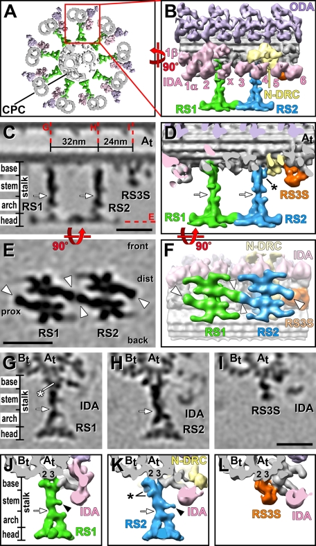
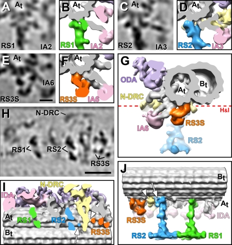
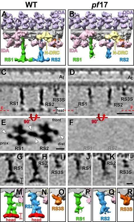
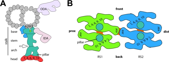
Radial spokes (RSs) play an essential role in the regulation of axonemal dynein activity and thus of ciliary and flagellar motility. However, few details are known about the complexes involved. Using cryo-electron tomography and subtomogram averaging, we visualized the three-dimensional structure of the radial spokes in Chlamydomonas flagella in unprecedented detail. Unlike many other species, Chlamydomonas has only two spokes per axonemal repeat, RS1 and RS2. Our data revealed previously uncharacterized features, including two-pronged spoke bases that facilitate docking to the doublet microtubules, and that inner dyneins connect directly to the spokes. Structures of wild type and the headless spoke mutant pf17 were compared to define the morphology and boundaries of the head, including a direct RS1-to-RS2 interaction. Although the overall structures of the spokes are very similar, we also observed some differences, corroborating recent findings about heterogeneity in the docking of RS1 and RS2. In place of a third radial spoke we found an uncharacterized, shorter electron density named "radial spoke 3 stand-in," which structurally bears no resemblance to RS1 and RS2 and is unaltered in the pf17 mutant. These findings demonstrate that radial spokes are heterogeneous in structure and may play functionally distinct roles in axoneme regulation.


Figures

FIGURE 1:
FIGURE 1:
3D structure of RSs in pWT. (A) Composite isosurface rendering of an axoneme cross section viewed from proximal (flagellar base) toward distal (flagellar tip). The CPC is surrounded by nine DMTs, one of which is boxed in red and shown in longitudinal orientation in B. (B–L) Isosurface renderings (B, D, F, J–L) and tomographic slices (C, E, G–I) show the averaged axonemal repeat in longitudinal views (B–F) from the front (B–D) and bottom (E–F; i.e., looking from the central pair toward the DMT), as well as in cross-sectional views (G–L). The structure of both RS1 (green) and RS2 (blue) can be separated into four regions: the two-pronged base closest to the DMT, the stem, the arch with two pillars, and the head domain closest to the CPC (C, D, G, H, J, K). Base, stem, and arch together represent the portion of the RS called the “stalk” in previous publications. White arrows in C, D, G, H, J and K indicate the waist, a narrow region that separates stem and arch; note the small protrusion from the stem (black arrowheads in J and K). (E, F) Bottom views of the two RS heads, revealing that each head consists of two rotationally symmetric halves; white arrowheads point to a region found in each of these four halves named the “ear.” The front, back, proximal (prox), and distal (dist) sides of the average are indicated in E for easier orientation in relation to the front view shown in C. Red dotted lines in C indicate the locations of the tomographic slices shown in E and G–I. Although both RSs and RS3S (orange) are attached to the same protofilaments A2 and A3 of the A tubule (At, 2, 3; G–L), the RS3S structure does not resemble any regions of RS1 or RS2. In contrast, the structures of RS1 and RS2 are very similar overall but also show several small differences: the base of RS2 is slightly larger than the RS1 base. The additional densities in RS2 are labeled with a black asterisk in D and K. The white asterisk in G points to a density present only in RS1. Other labels: B tubule (Bt), inner dynein arm heads (IDA 1α, 1β, 2–6, and x; rose), nexin–dynein regulatory complex (N-DRC, yellow), outer dynein arm (ODA, purple). Color coding of structures is preserved in all of the figures. Inner arm dyneins are numbered as in Nicastro et al. (2006). Scale bars, 25 nm; scale bar in I is applicable to G–I.
FIGURE 2:
FIGURE 2:
Connections between RSs and neighboring structures. Tomographic slices (A, C, E, H) and isosurface renderings (B, D, F, G, I, J) of the averaged axonemal repeat from pWT show the connections of the bases of RS1, RS2, and RS3S. (A–G) Cross-sectional views from proximal (A–F) and distal (G) reveal direct connections between the tails of several inner dynein arms and the RSs or RS3S: inner arm dynein IA2 attaches to the front of the RS1 base (A, B) and dynein IA3 to the front of the RS2 base (C, D). The RS3S forms a connection to the tail of inner arm dynein IA6 (E–G); this dynein tail also attaches to the A-tubule. (H, I) Longitudinal bottom views of the axonemal repeat cut through the base of the RSs, as indicated by a red dotted line in G, show that both RS1 and RS2 have two attachment sites to the A tubule (At). These attachment points lie within a plane that is roughly perpendicular to the DMT axis. In contrast, RS3S has three attachment sites to the A tubule, which are aligned roughly parallel to the DMT axis, that is, in a plane rotated ∼90° compared with the docking sites of RS1 and RS2. (J) A longitudinal view from the back side reveals the three docking points of the RS3S and connections to the N-DRC from both the base of RS2 (white arrows in I and J) and of RS3S (white arrowhead in I and J). Other labels: B tubule (Bt), inner dynein arm heads (IDA 2, 3, 6; rose), nexin–dynein regulatory complex (N-DRC, yellow), outer dynein arms (ODA, purple). Scale bars, 10 nm in E, applicable for A–E, and 25 nm in H.
FIGURE 3:
FIGURE 3:
Comparison of the RS structure in WT and the RS-headless mutant pf17. Isosurface renderings (A, B, M–R) and tomographic slices (C–L) from the averaged axonemal repeats of WT and pf17 viewed from the front (A–D), the bottom (E, F), and the proximal side (G–R) show a region defined as the RS head (colored red in M and N) missing in pf17. White arrowheads in E point to the ears of the RS head. The front, proximal (prox), and distal (dist) sides of the average are indicated in E for easier orientation in relation to the front view shown in C and D. Red dotted lines in C and D indicate the locations of the tomographic slices shown in E and F. Although both RS heads are missing in pf17, the RS3S (L, R) and other axonemal structures such as ODA, IDA, and N-DRC are unaffected. Other labels: inner dynein arm heads (IDA, rose), nexin–dynein regulatory complex (N-DRC, yellow), outer dynein arms (ODA, purple). Scale bars, 25 nm in D, 10 nm in E and L. Scale bars in D, E, and L are applicable for C, F, and G–K, respectively. Supplemental Figure S2 demonstrates that the defect observed in pf17 is due to lack of electron density in the region of the RS heads and is not caused by differences in the averaging quality and resolution.
FIGURE 4:
FIGURE 4:
Schematic model of the RS structure in Chlamydomonas flagella. (A) Cross-sectional view from proximal showing, in turquoise, the consensus structure of RSs, that is, the part of the RS that seems consistent between RS1 and RS2; colored in green is a density that is present in RS1 and absent in RS2, and shown in blue are densities that are present in RS2 and absent from RS1. The region depicted in red is the head that is missing in the mutant pf17. Combined with the results of previous comparative biochemical studies, our data suggest that RS proteins RSP1, 4, 6, 9, and 10 are in the red-colored head region. (B) Bottom view of the heads of RS1 (green) and RS2 (blue) in a similar orientation as shown in Figures 1, E and F, and 3E. The front, proximal (prox), and distal (dist) sides of the model are indicated for easier orientation. The head of each RS consists of two rotationally symmetric units, each of which likely contains at least one copy of each RS head protein. Turquoise circles indicate the positions where the arch's pillars connect to the RS heads. Connections between the symmetric halves are shown in orange. The heads of RS1 and RS2 connect through the front and back ears, respectively.

References

    1. Afzelius BA. Cilia-related diseases. J Pathol. 2004;204:470–477. - PMC - PubMed
    1. Bui KH, Sakakibara H, Movassagh T, Oiwa K, Ishikawa T. Molecular architecture of inner dynein arms in situ in Chlamydomonas reinhardtii flagella. J Cell Biol. 2008;183:923–932. - PMC - PubMed
    1. Chasey D. Further observations on the ultrastructure of cilia from Tetrahymena pyriformis. Exp Cell Res. 1972;74:471–479. - PubMed
    1. Chasey D. The three-dimensional arrangement of radial spokes in the flagella of Chlamydomonas reinhardtii. Exp Cell Res. 1974;84:374–380. - PubMed
    1. Curry AM, Rosenbaum JL. Flagellar radial spoke: a model molecular genetic system for studying organelle assembly. Cell Motil Cytoskeleton. 1993;24:224–232. - PubMed

Publication types

LinkOut - more resources