

Double-clad fiber with a tapered end for confocal endomicroscopy
- PMID: 22076259
- PMCID: PMC3207367
- DOI: 10.1364/BOE.2.002961
Double-clad fiber with a tapered end for confocal endomicroscopy
Abstract
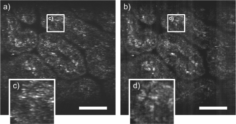
We present a double-clad fiber coupler (DCFC) for use in confocal endomicroscopy to reduce speckle contrast, increase signal collection while preserving optical sectioning. The DCFC is made by incorporating a double-clad tapered fiber (DCTF) to a fused-tapered DCFC for achromatic transmission (from 1265 nm to 1325 nm) of > 95% illumination light trough the single mode (SM) core and collection of > 40% diffuse light through inner cladding modes. Its potential for confocal endomicroscopy is demonstrated in a spectrally-encoded imaging setup which shows a 3 times reduction in speckle contrast as well as 5.5 × increase in signal collection compared to imaging with a SM fiber.
Keywords: (030.6140) Speckle; (060.2340) Fiber optics components; (110.2990) Image formation theory; (170.1790) Confocal microscopy; (170.2150) Endoscopic imaging.
Figures
Similar articles
-
Double-clad fiber coupler for endoscopy.Opt Express. 2010 May 10;18(10):9755-64. doi: 10.1364/OE.18.009755. Opt Express. 2010. PMID: 20588826
-
Double-clad fiber coupler for partially coherent detection.Opt Express. 2015 Apr 6;23(7):9040-51. doi: 10.1364/OE.23.009040. Opt Express. 2015. PMID: 25968739
-
Asymmetric double-clad fiber couplers for endoscopy.Opt Lett. 2013 Nov 1;38(21):4514-7. doi: 10.1364/ol.38.004514. Opt Lett. 2013. PMID: 24177133
-
Laser tissue coagulation and concurrent optical coherence tomography through a double-clad fiber coupler.Biomed Opt Express. 2015 Mar 16;6(4):1293-303. doi: 10.1364/BOE.6.001293. eCollection 2015 Apr 1. Biomed Opt Express. 2015. PMID: 25909013 Free PMC article.
-
Confocal endomicroscopy: instrumentation and medical applications.Ann Biomed Eng. 2012 Feb;40(2):378-97. doi: 10.1007/s10439-011-0426-y. Epub 2011 Oct 13. Ann Biomed Eng. 2012. PMID: 21994069 Free PMC article. Review.
Cited by
-
Double-Clad Fiber-Based Multifunctional Biosensors and Multimodal Bioimaging Systems: Technology and Applications.Biosensors (Basel). 2022 Feb 1;12(2):90. doi: 10.3390/bios12020090. Biosensors (Basel). 2022. PMID: 35200350 Free PMC article. Review.
-
Spectrally encoded coherence tomography and reflectometry: Simultaneous en face and cross-sectional imaging at 2 gigapixels per second.J Biophotonics. 2018 Apr;11(4):e201700268. doi: 10.1002/jbio.201700268. Epub 2017 Dec 27. J Biophotonics. 2018. PMID: 29149542 Free PMC article.
References
-
- Kiesslich R., Burg J., Vieth M., Gnaendiger J., Enders M., Delaney P., Polglase A., McLaren W., Janell D., Thomas S., Nafe B., Galle P. R., Neurath M. F., “Confocal laser endoscopy for diagnosing intraepithelial neoplasias and colorectal cancer in vivo,” Gastroenterology 127, 706–713 (2004).10.1053/j.gastro.2004.06.050 - DOI - PubMed
-
- Buchner A. M., Shahid M. W., Heckman M. G., Krishna M., Ghabril M., Hasan M., Crook J. E., Gomez V., Raimondo M., Woodward T., Wolfsen H. C., Wallace M. B., “Comparison of probe-based confocal laser endomicroscopy with virtual chromoendoscopy for classification of colon polyps,” Gastroenterology 138, 834–842 (2010).10.1053/j.gastro.2009.10.053 - DOI - PubMed
-
- Carlson K., Pavlova I., Collier T., Descour M., Follen M., Richards-Kortum R., “Confocal microscopy: Imaging cervical precancerous lesions,” Gynecologic Oncology 99, S84–S88 (2005), The 4th International Conference on Cervical Cancer with a Day of Spiritual, Psychological, Complementary, and Alternative Treatment of Cancer and Pain.10.1016/j.ygyno.2005.07.049 - DOI - PubMed
LinkOut - more resources
Full Text Sources
Other Literature Sources