. 2011 Dec 8;7(1):12-23.
doi: 10.1038/nprot.2011.413.

Construction of implantable optical fibers for long-term optogenetic manipulation of neural circuits

Affiliations

Construction of implantable optical fibers for long-term optogenetic manipulation of neural circuits

Dennis R Sparta et al. Nat Protoc. .

Abstract

In vivo optogenetic strategies have redefined our ability to assay how neural circuits govern behavior. Although acutely implanted optical fibers have previously been used in such studies, long-term control over neuronal activity has been largely unachievable. Here we describe a method to construct implantable optical fibers to readily manipulate neural circuit elements with minimal tissue damage or change in light output over time (weeks to months). Implanted optical fibers readily interface with in vivo electrophysiological arrays or electrochemical detection electrodes. The procedure described here, from implant construction to the start of behavioral experimentation, can be completed in approximately 2-6 weeks. Successful use of implantable optical fibers will allow for long-term control of mammalian neural circuits in vivo, which is integral to the study of the neurobiology of behavior.


Figures

Figure 1
Figure 1
Light transmission from implantable optical fibers before and after implantation. (a) Optical fibers before implantation transmitted 85.2 ± 2.8% of the light from the patch cable. After 6 weeks in brain tissue, the same optical fibers transmitted 81.1 ± 3.1% of the light from the patch cable (n = 10 implanted optical fibers). (b) Photomicrograph of the ventral tegmental area depicting typical damage associated with the implantation of an optical fiber that was secured in the brain for 8 weeks. Cell nuclei are shown in blue (DAPI ) and neurons expressing opsin proteins are shown in green.
Figure 2
Figure 2
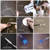
Construction of implantable optical fibers. (a) A stripped and cut piece of optical fiber for construction of implantable optical fiber. (b) The optical fiber is inserted into the ferrule and secured in place by epoxy. (c) The optical fiber is scored to cleave it at the convex side of the ferrule. (d) The convex side of the ferrule is polished using progressively finer grades of polishing paper. (e) The optical fiber is scored to break at the appropriate length for implantation into the brain. (f) The finished implantable optical fiber.
Figure 3
Figure 3
Construction of patch cables for use in in vivo optogenetic experiments. (a) The unstripped optical fiber is threaded through furcation tubing. (b) The protective coating lining the optical fiber is stripped off using a fiber stripper tool. (c) The stripped optical fiber is inserted into the epoxy filled FC connector. (d) The optical fiber protruding from the FC ferrule is scored and cleaved. The protective boot is secured to the FC connector. (e) The ferrule side of the FC connector is inserted into the polishing disc. The ferrule is polished using progressively finer grades of polishing paper. (f) The 1.25-mm ferrule is epoxied and polished at the other end of the patch cable. The exposed fiber is epoxied to the ferrule and furcation tubing to provide additional structural stability. Heat-shrink tubing slides over top of the epoxy bead and the ferrule to prevent light transmission that could be visible to the subject. (g) Implantable optical fiber is interfaced with the patch cable using a ceramic split sleeve. (h) Light transmission through the implantable optical fiber should be uniform and concentric. Light output from the implant should be > 70% of the input light from the patch cable. (i) Nonconcentric, uneven light output from the implant indicates a nonviable implantable optical fiber. These should be discarded.
Figure 4
Figure 4
Interfacing implantable optical fibers with in vivo electrophysiological arrays. (a) An optical fiber mount that is constructed out of stainless steel tubing is epoxied to the multiunit electrode array. (b) The implantable optical fiber is mounted and secured to the optical fiber mount located on the array. (c) The finished optrode is connected to the stereotaxic adapter and is ready for implantation.
Figure 5
Figure 5
Implantation of optical fibers. (a) The stereotaxic adapter for implantation of optical fibers. (b) The stereotaxic adapter interfaced with an implantable optical fiber is secured to the stereotaxic arm. (c) Anchoring screws are secured to the skull and the implantable optical fibers are slowly lowered into the brain tissue. (d) The implanted optical fibers are secured into place with headcap cement. (e) After surgery, optical fiber protectors are placed over the implanted optical fibers to prevent damage to the fiber cores. (f) Before behavioral experimentation, optical patch cables are connected to the implanted optical fibers.

References

    1. Claridge-Chang A, et al. Writing memories with light-addressable reinforcement circuitry. Cell. 2009;139:405–415. - PMC - PubMed
    1. Guo ZV, Hart AC, Ramanathan S. Optical interrogation of neural circuits in Caenorhabditis elegans. Nat. Methods. 2009;6:891–896. - PMC - PubMed
    1. Liewald JF, et al. Optogenetic analysis of synaptic function. Nat. Methods. 2008;5:895–902. - PubMed
    1. Zhu P, et al. Optogenetic dissection of neuronal circuits in zebrafish using viral gene transfer and the Tet system. Front. Neural Circuits. 2009;3:21. - PMC - PubMed
    1. Tsai HC, et al. Phasic firing in dopaminergic neurons is sufficient for behavioral conditioning. Science (New York, NY) 2009;324:1080–1084. - PMC - PubMed

Publication types

MeSH terms