Review
. 2011;11(8):7773-98.
doi: 10.3390/s110807773. Epub 2011 Aug 8.

A review of optical NDT technologies

Affiliations
Review

A review of optical NDT technologies

Yong-Kai Zhu et al. Sensors (Basel). 2011.

Abstract

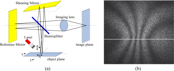
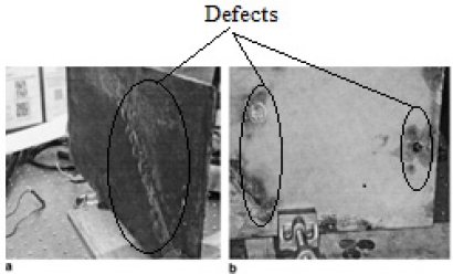
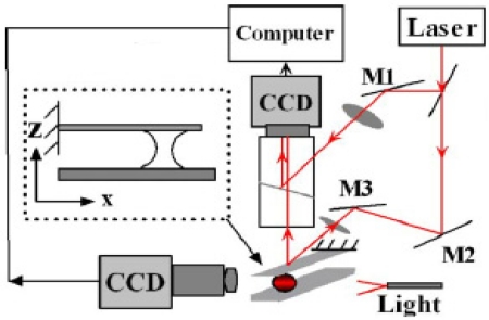
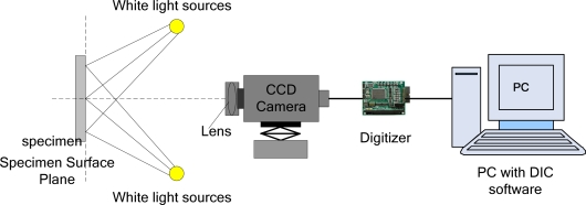
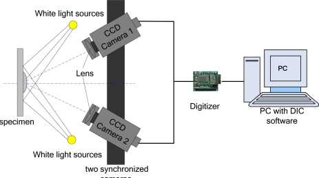
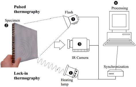
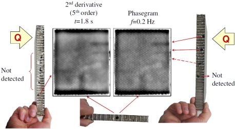
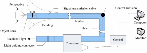
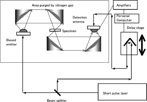
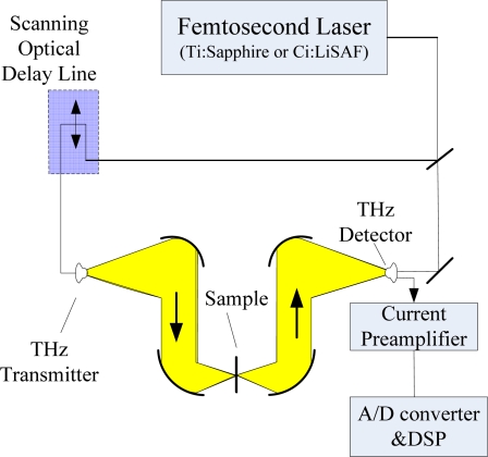
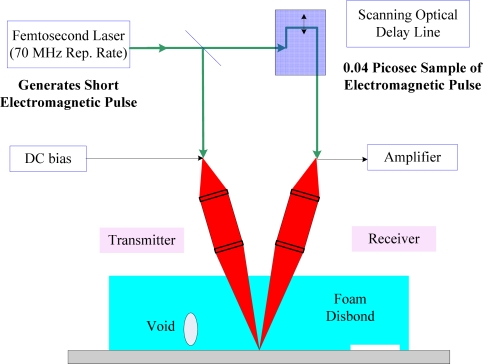
Optical non-destructive testing (NDT) has gained more and more attention in recent years, mainly because of its non-destructive imaging characteristics with high precision and sensitivity. This paper provides a review of the main optical NDT technologies, including fibre optics, electronic speckle, infrared thermography, endoscopic and terahertz technology. Among them, fibre optics features easy integration and embedding, electronic speckle focuses on whole-field high precision detection, infrared thermography has unique advantages for tests of combined materials, endoscopic technology provides images of the internal surface of the object directly, and terahertz technology opens a new direction of internal NDT because of its excellent penetration capability to most of non-metallic materials. Typical engineering applications of these technologies are illustrated, with a brief introduction of the history and discussion of recent progress.

Keywords: endoscopic; infrared thermography; optical non-destructive testing (NDT); speckle; terahertz (THz) technology.


Figures

Figure 1.
Figure 1.
The FBG sensors installed on the Tsing Ma bridge at (1) hanger cable, (2) rocker bearing, (3) truss girders of section Chainage 23488. Reproduced with permission from [9], copyright 2006, Elsevier.
Figure 2.
Figure 2.
The detail view of FBG sensors installed on (1) hanger cable, (2) rocker bearing, (3) truss girders of section Chainage 23488. Reproduced with permission from [9], copyright 2006, Elsevier.
Figure 3.
Figure 3.
A structure of optical fibre polarization sensor detecting system. Reproduced with permission from [11], copyright 2000, Elsevier.
Figure 4.
Figure 4.
Out-of-plane ESPI system.
Figure 5.
Figure 5.
(a) Out-of-plane Electronic Shearography; (b) A shearography correlation fringle pattern. Reproduced with permission from [18], copyright 2010, IOP.
Figure 6.
Figure 6.
The testing sample for ESPI. Reproduced with permission from [23], copyright 2006, Elsevier.
Figure 7.
Figure 7.
Experimental setup of micro-ESPI system. Reproduced with permission from [25], copyright 2006, American Institute of Physics.
Figure 8.
Figure 8.
Schematic of 2-D DIC system.
Figure 9.
Figure 9.
Schematic of a complete 3-D DIC system.
Figure 10.
Figure 10.
The experimental detection devices. Reproduced with permission from [58], copyright 2010, IOP.
Figure 11.
Figure 11.
The surface thermal images of the sample. Reproduced with permission from [58], copyright 2010, IOP.
Figure 12.
Figure 12.
Minor collision defects in the carbon fibre composite plate thermal images: (a) Thermographic magnitude image; (b) Phase image. Reproduced with permission from [59], copyright 1998, Elsevier.
Figure 13.
Figure 13.
A sample with eight different sizes and depths holes. Reproduced with permission from [60], copyright 2006, Elsevier.
Figure 14.
Figure 14.
The thermographs of concrete samplea, top ones are thermograms, bottom ones are respective phase images. Reproduced with permission from [61], copyright 1999, Elsevier.
Figure 15.
Figure 15.
Japanese Heights State University thermography NDT systems. Reproduced with permission from [61], copyright 1999, Elsevier.
Figure 16.
Figure 16.
Basic configuration of pulsed eddy current thermography system. Reproduced with permission from [63], copyright 2010, Elsevier.
Figure 17.
Figure 17.
The structure of electronic endoscope.
Figure 18.
Figure 18.
A standard THz-TDS imaging system. Reproduced with permission from [75], copyright 2007, IEEE.
Figure 19.
Figure 19.
T-ray imager schematic. Reproduced with permission from [76], copyright 2002, IEEE.
Figure 20.
Figure 20.
A reflected pulse THz systems used for detection of SOFI [78].

References

    1. Xiao NH. New Technologies and Technical Standards for Modern Non-Destructive Testing Technology and Application. Beijing Silver Sound Audiovisual Press; Beijing, China: 2004. (in Chinese).
    1. McCann DM, Forde MC. Review of NDT methods in the assessment of concrete and masonry structures. NDT&E Int. 2001;34:71–84.
    1. Shen GT. Review of non-destructive testing in China. Insight. 2006;48:398–401.
    1. Ansari F. State-of-the-art in the applications of fibre-optic sensors to cementitious composites. Cem. Concr. Compos. 1997;19:3–19.
    1. Lin YB, Lai JS, Chang KC, Li LS. Flood scour monitoring system using fibre bragg grating sensors. Smart Mater. Struct. 2006;15:1950–1959.

Publication types

LinkOut - more resources