Review
. 2011 Dec 1;50(34):H253-64.
doi: 10.1364/AO.50.00H253.

Partially coherent lensfree tomographic microscopy [Invited]

Affiliations
Review

Partially coherent lensfree tomographic microscopy [Invited]

Serhan O Isikman et al. Appl Opt. .

Abstract

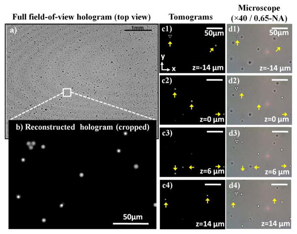
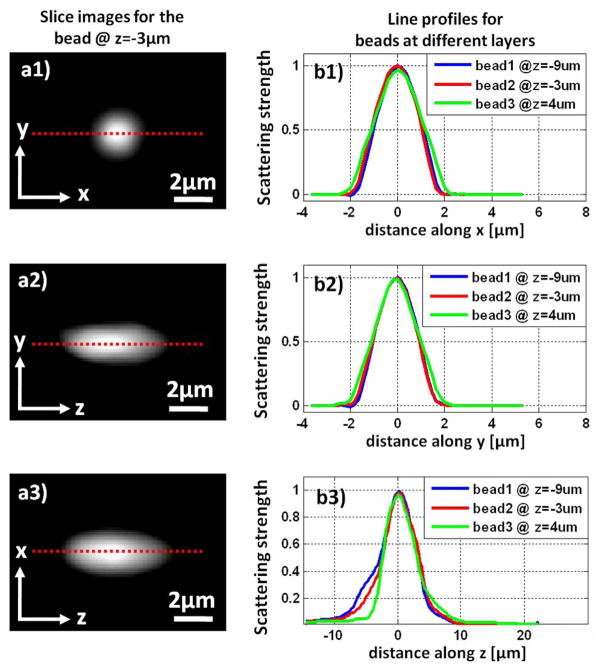
Optical sectioning of biological specimens provides detailed volumetric information regarding their internal structure. To provide a complementary approach to existing three-dimensional (3D) microscopy modalities, we have recently demonstrated lensfree optical tomography that offers high-throughput imaging within a compact and simple platform. In this approach, in-line holograms of objects at different angles of partially coherent illumination are recorded using a digital sensor-array, which enables computing pixel super-resolved tomographic images of the specimen. This imaging modality, which forms the focus of this review, offers micrometer-scale 3D resolution over large imaging volumes of, for example, 10-15 mm(3), and can be assembled in light weight and compact architectures. Therefore, lensfree optical tomography might be particularly useful for lab-on-a-chip applications as well as for microscopy needs in resource-limited settings.


Figures

Fig. 1
Fig. 1
(Color online) Shows an illustration of the lensfree on-chip holography platform. The objects are placed on the top of an optoelectronic sensor array, with < 4 mm distance to its active area. The sensor records the holograms of objects as a partially coherent light source, such as an LED placed ~40–100 mm away from the sensor, provides illumination. The LED illumination is spatially filtered by an aperture of diameter (D) of ~0.05–0.1 mm. Since holograms are recorded with unit fringe-magnification, imaging FOV equals the active area of the sensor, e.g., 24 mm2.
Fig. 2
Fig. 2
(a) Shows a recorded lower-resolution (LR) hologram of a “UCLA” pattern etched on glass using focused-ion beam (FIB) milling. The aliasing artifacts can be observed in the fringes away from the hologram center. (b) Shows the pixel super-resolved (SR) hologram synthesized by using multiple (~15–20) slightly shifted LR holograms, one of which is shown in (a). (c) and (d) show the reconstructed phase images using the LR and SR holograms, respectively. The color-bar applies to the reconstructed phase images in (c) and (d), and its unit is radians.
Fig. 3
Fig. 3
(a1–a3) Show slice images (for a microsphere with 2 μm diameter) in x-y, y-z and x-z planes, respectively, obtained by reconstructing a raw LR hologram at different depths along the optic axis (z-axis). (b1–b3) Similar to (a1–a3), but obtained by reconstructing an SR hologram of the same microparticle. View 1 and View 2 provide the full 3D datasets for LR and SR reconstructions, respectively.
Fig. 4
Fig. 4
(Color online) (a) Shows the schematic illustration of the bench-top implementation of lensfree optical tomography system. The sample is sequentially illuminated from multiple angles, and PSR is employed at each angle to obtain high-resolution projection images for different viewing directions. (b) Illustrates the field-portable tomographic microscope that weighs only ~110 grams, particularly designed for low-resource settings. Multimode optical fibers (with ~0.1 mm core diameter) are electromagnetically actuated to record subpixel shifted holograms and achieve PSR. (c) A photograph of the field-portable tomographic microscope is shown.
Fig. 5
Fig. 5
(a1–a3) Shows the cropped PSR holograms for three different angles of partially coherent illumination. The sample is a chamber filled with randomly distributed microspheres with 2 μm diameter. (b1–b3) Shows the projection images obtained by reconstructing the holograms in (a1–a3). These images are registered with respect to the same microparticle that is seen at the center of each projection image. The microparticles in the projection images are indeed at different depth layers, as a result of which the projection images look different at different angles. Nevertheless, due to the low axial-resolution of in-line holography, all the particles appear to be in-focus in each image.
Fig. 6
Fig. 6
(Color online) (a) Shows a recorded hologram with 24 mm2 FOV for the case of vertical illumination. (b) Shows the holographic reconstruction for a small region-of-interest within the large imaging FOV, where all the beads appear in-focus. (c1–c4) Show depth-resolved slice images in the x-y plane for different depths, obtained by tomographic reconstruction. The sectioning results provided by lensfree optical tomography can be compared against the section images in (d1–d4) obtained using a conventional bright-field microscope (0.65-NA) that focused at different depth layers. Full 3D datasets for computed tomograms are provided in View 3.
Fig. 7
Fig. 7
(Color online) (a1–a3) Show slice images for a 2 μm bead in the x-y, y-z and x-z planes, respectively. Since the tomograms are computed with a dual-axis scheme (light source is rotated along x and y axes, sequentially), the x-y cross-section does not show any asymmetrical artifacts that are normally observed in limited-angle single-axis tomography. On the other hand, the elongation in the axial direction is not entirely eliminated. (b1–b3) Show the line profiles for beads at three different depth regions in the camber. The FWHM values for the lateral line profiles (along x and y) are measured as ~2.2 μm, while the axial FWHM is ~5.5 μm.
Fig. 8
Fig. 8
(Color online) Shows the change in lateral (left) and axial (right) resolution as the sample-to-sensor distance (z2) is increased. Spatial resolution achieved by lensfree tomography degrades approximately by a factor of 2 at z2 ~ 4 mm compared to z2 ~ 1 mm.

References

    1. Gabor D. A new microscopic principle. Nature. 1948;161:777–778. - PubMed
    1. Garcia-Sucerquia J, Xu W, Jericho SK, Klages P, Jericho MH, Kreuzer HJ. Digital in-line holographic microscopy. Appl Opt. 2006;45:836–850. - PubMed
    1. Xu W, Jericho MH, Meinertzhagen IA, Kreuzer HJ. Digital in-line holography for biological applications. Proc Natl Acad Sci USA. 2001;98:11301–11305. - PMC - PubMed
    1. Leith EN, Upatnieks J, Haines KA. Microscopy by wavefront reconstruction. J Opt Soc Am. 1965;55:981–986.
    1. Schnars U, Jüptner W. Direct recording of holograms by a CCD target and numerical reconstruction. Appl Opt. 1994;33:179–181. - PubMed

Publication types

MeSH terms