

View angle tilting echo planar imaging for distortion correction
- PMID: 22213567
- PMCID: PMC3323714
- DOI: 10.1002/mrm.23320
View angle tilting echo planar imaging for distortion correction
Abstract
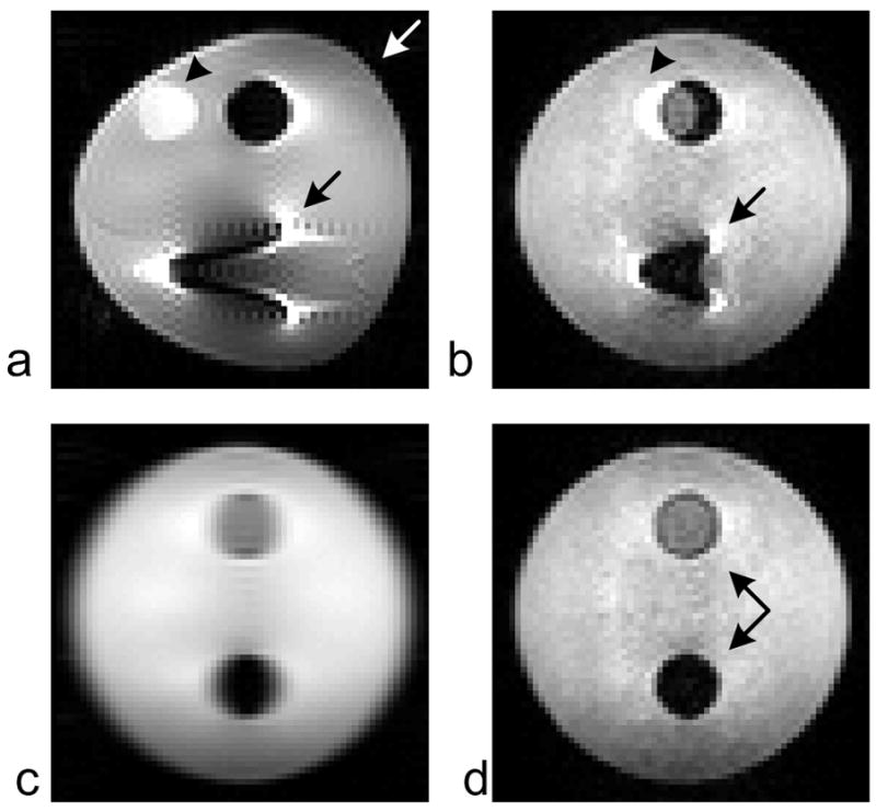
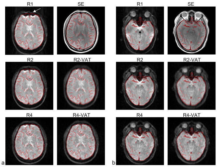
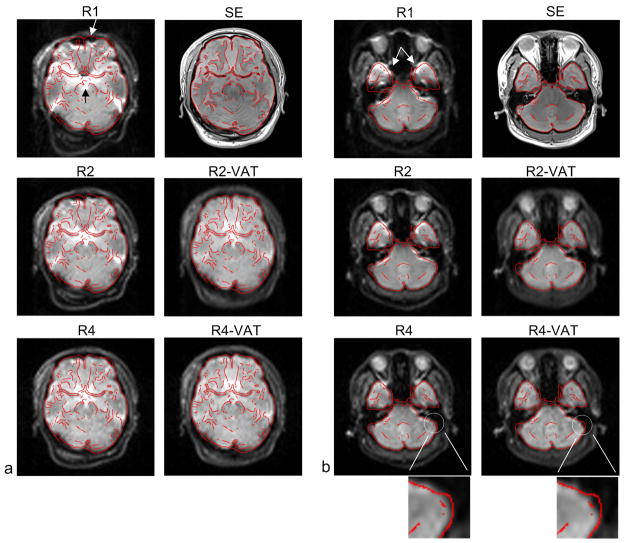
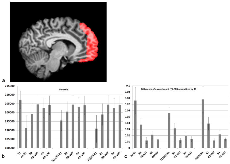
Geometric distortion caused by field inhomogeneity along the phase-encode direction is one of the most prominent artifacts due to a relatively low effective bandwidth along that direction in magnetic resonance echo planar imaging. This work describes a method for correcting in-plane image distortion along the phase-encode direction using a view angle tilting imaging technique in spin-echo echo planar imaging. Spin-echo echo planar imaging with view angle tilting uses the addition of gradient blips along the slice-select direction, concurrently applied with the phase-encode gradient blips, producing an additional phase. This phase effectively offsets an unwanted phase accumulation caused by field inhomogeneity, resulting in the removal of image distortion along the phase-encode direction. The proposed method is simple and straightforward both in implementation and application with no scan time penalty. Therefore, it is readily applicable on commercial scanners without having any customized postprocessing. The efficacy of the spin-echo echo planar imaging with view angle tilting technique in the correction of image distortion is demonstrated in phantom and in vivo brain imaging.
Copyright © 2011 Wiley Periodicals, Inc.
Figures


Similar articles
-
A hybrid strategy for correcting geometric distortion in echo-planar images.Magn Reson Imaging. 2014 Jun;32(5):590-3. doi: 10.1016/j.mri.2014.02.011. Epub 2014 Feb 14. Magn Reson Imaging. 2014. PMID: 24650682
-
Accelerated point spread function mapping using signal modeling for accurate echo-planar imaging geometric distortion correction.Magn Reson Med. 2013 Jun;69(6):1650-6. doi: 10.1002/mrm.24396. Epub 2012 Jul 17. Magn Reson Med. 2013. PMID: 22807105
-
Two-dimensional phase correction method for single and multi-shot echo planar imaging.Magn Reson Med. 2011 Dec;66(6):1616-26. doi: 10.1002/mrm.22958. Epub 2011 May 13. Magn Reson Med. 2011. PMID: 21574178
-
Time-varying view angle tilting with spiral readout gradients.Magn Reson Med. 2012 Oct;68(4):1220-7. doi: 10.1002/mrm.24125. Epub 2011 Dec 28. Magn Reson Med. 2012. PMID: 22213151
-
Prospective and retrospective high order eddy current mitigation for diffusion weighted echo planar imaging.Magn Reson Med. 2013 Nov;70(5):1293-305. doi: 10.1002/mrm.24589. Epub 2013 Jan 16. Magn Reson Med. 2013. PMID: 23325564
Cited by
-
Induced magnetic moment in stainless steel components of orthodontic appliances in 1.5 T MRI scanners.Med Phys. 2015 Oct;42(10):5871-8. doi: 10.1118/1.4930796. Med Phys. 2015. PMID: 26429261 Free PMC article.
References
-
- Mansfield P. Multi-Planar Image-Formation Using NMR Spin Echoes. Journal of Physics C-Solid State Physics. 1977;10(3):L55–L58.
-
- Reber PJ, Wong EC, Buxton RB, Frank LR. Correction of off resonance-related distortion in echo-planar imaging using EPI-based field maps. Magn Reson Med. 1998;39(2):328–330. - PubMed
-
- Jezzard P, Balaban RS. Correction for geometric distortion in echo planar images from B0 field variations. Magn Reson Med. 1995;34(1):65–73. - PubMed
-
- Wan X, Gullberg GT, Parker DL, Zeng GL. Reduction of geometric and intensity distortions in echo-planar imaging using a multireference scan. Magn Reson Med. 1997;37(6):932–942. - PubMed
-
- Chen NK, Wyrwicz AM. Correction for EPI distortions using multi-echo gradient-echo imaging. Magn Reson Med. 1999;41(6):1206–1213. - PubMed
Publication types
MeSH terms
Grants and funding
LinkOut - more resources
Full Text Sources
Other Literature Sources
