

Multicontrast x-ray computed tomography imaging using Talbot-Lau interferometry without phase stepping
- PMID: 22225312
- PMCID: PMC3261056
- DOI: 10.1118/1.3672163
Multicontrast x-ray computed tomography imaging using Talbot-Lau interferometry without phase stepping
Abstract
Purpose: The purpose of this work is to demonstrate that multicontrast computed tomography (CT) imaging can be performed using a Talbot-Lau interferometer without phase stepping, thus allowing for an acquisition scheme like that used for standard absorption CT.
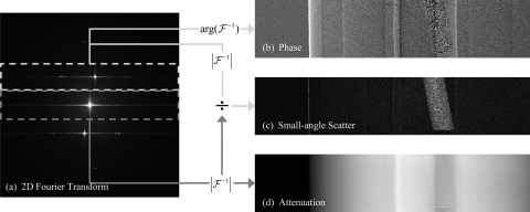
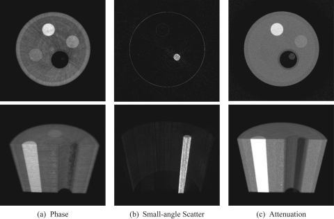
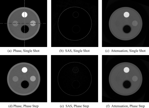
Methods: Rather than using phase stepping to extract refraction, small-angle scattering (SAS), and absorption signals, the two gratings of a Talbot-Lau interferometer were rotated slightly to generate a moiré pattern on the detector. A Fourier analysis of the moiré pattern was performed to obtain separate projection images of each of the three contrast signals, all from the same single-shot of x-ray exposure. After the signals were extracted from the detector data for all view angles, image reconstruction was performed to obtain absorption, refraction, and SAS CT images. A physical phantom was scanned to validate the proposed data acquisition method. The results were compared with a phantom scan using the standard phase stepping approach.
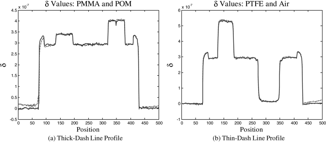
Results: The reconstruction of each contrast mechanism produced the expected results. Signal levels and contrasts match those obtained using the phase stepping technique.
Conclusions: Absorption, refraction, and SAS CT imaging can be achieved using the Talbot-Lau interferometer without the additional overhead of long scan time and phase stepping.
Figures
Similar articles
-
The second-order differential phase contrast and its retrieval for imaging with x-ray Talbot interferometry.Med Phys. 2012 Dec;39(12):7237-53. doi: 10.1118/1.4764901. Med Phys. 2012. PMID: 23231275
-
Empirical beam hardening and ring artifact correction for x-ray grating interferometry (EBHC-GI).Med Phys. 2021 Mar;48(3):1327-1340. doi: 10.1002/mp.14672. Epub 2021 Jan 10. Med Phys. 2021. PMID: 33338261
-
A preclinical Talbot-Lau prototype for x-ray dark-field imaging of human-sized objects.Med Phys. 2018 Jun;45(6):2565-2571. doi: 10.1002/mp.12889. Epub 2018 Apr 27. Med Phys. 2018. PMID: 29582440
-
Comparison of methods for sensitivity correction in Talbot-Lau computed tomography.Int J Comput Assist Radiol Surg. 2021 Dec;16(12):2099-2106. doi: 10.1007/s11548-021-02487-x. Epub 2021 Sep 9. Int J Comput Assist Radiol Surg. 2021. PMID: 34499282 Free PMC article. Review.
-
Review and experimental verification of x-ray dark-field signal interpretations with respect to quantitative isotropic and anisotropic dark-field computed tomography.Phys Med Biol. 2020 Nov 27;65(23):235017. doi: 10.1088/1361-6560/abb7c6. Phys Med Biol. 2020. PMID: 32916662 Review.
Cited by
-
Grating-based phase contrast tomosynthesis imaging: proof-of-concept experimental studies.Med Phys. 2014 Jan;41(1):011903. doi: 10.1118/1.4835455. Med Phys. 2014. PMID: 24387511 Free PMC article.
-
Helical X-ray phase-contrast computed tomography without phase stepping.Sci Rep. 2016 Apr 7;6:23953. doi: 10.1038/srep23953. Sci Rep. 2016. PMID: 27052368 Free PMC article.
-
Is high sensitivity always desirable for a grating-based differential phase contrast imaging system?Med Phys. 2020 Mar;47(3):1215-1228. doi: 10.1002/mp.13984. Epub 2020 Jan 20. Med Phys. 2020. PMID: 31872886 Free PMC article.
-
Acquisition of a single grid-based phase-contrast X-ray image using instantaneous frequency and noise filtering.Biomed Eng Online. 2022 Dec 27;21(1):92. doi: 10.1186/s12938-022-01061-z. Biomed Eng Online. 2022. PMID: 36575491 Free PMC article.
-
Imaging liver lesions using grating-based phase-contrast computed tomography with bi-lateral filter post-processing.PLoS One. 2014 Jan 17;9(1):e83369. doi: 10.1371/journal.pone.0083369. eCollection 2014. PLoS One. 2014. PMID: 24465378 Free PMC article.
References
-
- Momose A., Kawamoto S., Koyama I., Hamaishi Y., Takai H., and Suzuki Y., “Demonstration of x-ray talbot interferometry,” Jpn. J. Appl. Phys., Part 2 42, 866–868 (2003). 10.1143/JJAP.42.L866 - DOI
-
- Zanette I., Bech M., Pfeiffer F., and Weitkamp T., “Interlaced phase stepping in phase-contrast x-ray tomography,” Appl. Phys. Lett. 98, 094101 (2011).10.1063/1.3559849 - DOI
Publication types
MeSH terms
Grants and funding
LinkOut - more resources
Full Text Sources
Other Literature Sources
Medical
