. 2012 Jan 10;7(3):180-4.
doi: 10.1038/nnano.2011.249.

Vertical nanowire electrode arrays as a scalable platform for intracellular interfacing to neuronal circuits

Affiliations

Vertical nanowire electrode arrays as a scalable platform for intracellular interfacing to neuronal circuits

Jacob T Robinson et al. Nat Nanotechnol. .

Abstract

Deciphering the neuronal code--the rules by which neuronal circuits store and process information--is a major scientific challenge. Currently, these efforts are impeded by a lack of experimental tools that are sensitive enough to quantify the strength of individual synaptic connections and also scalable enough to simultaneously measure and control a large number of mammalian neurons with single-cell resolution. Here, we report a scalable intracellular electrode platform based on vertical nanowires that allows parallel electrical interfacing to multiple mammalian neurons. Specifically, we show that our vertical nanowire electrode arrays can intracellularly record and stimulate neuronal activity in dissociated cultures of rat cortical neurons and can also be used to map multiple individual synaptic connections. The scalability of this platform, combined with its compatibility with silicon nanofabrication techniques, provides a clear path towards simultaneous, high-fidelity interfacing with hundreds of individual neurons.


Figures
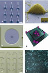
Figure 1
Figure 1. Vertical nanowire electrode array (VNEA) for interrogating neuronal networks
a, Scanning electron microscope (SEM) image of the 9 silicon nanowires that constitute the active region of a VNEA. Dimensions of the nanowire electrodes were designed to facilitate single-cell intracellular electrical coupling. False coloring shows metal-coated tips (gray) and insulating silicon oxide (blue). Scale bar, 1 µm. b, SEM image of a VNEA pad. False coloring indicates additional insulation by Al2O3 (green). Scale bar, 10 µm. c, SEM image of a device consisting of 16 stimulation/recording pads for parallel multi-site interrogation of neuronal circuits. Scale bar, 120 µm. d, SEM image of a rat cortical cell (3 days in vitro (DIV), false colored yellow) on top of a VNEA pad (false colored blue), showing nanowires interfacing with the cellular membrane (inset). e, Reconstructed three-dimensional confocal microscope image of rat cortical neurons cultured on a VNEA pad (3 DIV). f, Representative optical microscope image of calcein AM-labeled rat cortical neurons (cyan) cultured on a VNEA (5 DIV).
Figure 2
Figure 2. Characterization of the VNEA-cell electrical interface
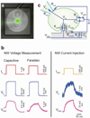
a, Composite bright field and fluorescence image of a patched HEK293 cell on a VNEA pad (0 DIV). Calcein (green) was added to the intracellular recording solution to enable fluorescence imaging of the patched cell. b, In both capacitive and Faradaic modes, the voltage response of the cell due to pipette current injection (Ip) (red) was recorded simultaneously using a patch pipette (Vp, blue) and a VNEA pad (VNW, magenta). Similarly, the cell’s membrane potential could be controlled (as verified by patch pipette recordings) by injecting current through the nanowires (INW) (orange). Note that capacitive and Faradaic measurements were performed on different cells since switching between recording modes required swapping amplifier electronics. c, Equivalent circuit model of the VNEA-cell interface. Ra,NW and Rs,NW (Ra,p and Rs,p) represent the access and seal resistances for the nanowires (pipette), respectively. The capacitance of the electrical double layer at the nanowire surface is represented as CNW. The equivalent circuit also includes the leak resistance due to uncoupled nanowires or defects in electrode insulation (RL) and the parasitic capacitance due to the device and associated electronics (Cp). The cell itself has a characteristic membrane resistance (Rm), capacitance (Cm) and resting potential (Vrest), all of which combine to determine the potential across the cell membrane (Vm). The values of these circuit elements were determined based on simultaneous patch pipette and VNEA measurements such as those shown in b.
Figure 3
Figure 3. Stimulation and recording of rat cortical neurons using a VNEA
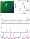
a, Representative differential interference contrast micrograph of a rat cortical neuron cultured on a VNEA pad (6 DIV). b, Probability of action potential (AP) excitation plotted as a function of current injected by nanowires shows a sigmoidal dependence (dashed line), which is similar to AP excitation elicited via intracellular patch pipettes. Probabilities were calculated for 20 trials and plotted as a function of the stimulation current. Error bars represent 95% confidence intervals. inset, 5 consecutive time-aligned APs stimulated by nanowire current injection show less than 1-ms jitter. c, APs were reliably stimulated by voltage pulses at the VNEA pad (magenta) and recorded using a patch pipette (blue). d, Similarly, APs were stimulated using a patch pipette (blue) and recorded by the VNEA pad in the Faradaic mode (magenta). VNEA measurements show good agreement with those obtained simultaneously via patch pipette.
Figure 4
Figure 4. Identification of functional synaptic connectivity using a VNEA and a patch pipette
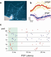
a, Composite bright field and fluorescence image of a cortical neuron patched and backfilled with calcein (14 DIV). b, Representative EPSPs (top) and IPSPs (bottom) were averaged (bold) and used as templates for identifying other PSPs recorded via a patch pipette. To measure these PSP events, we injected a constant current through the patch pipette to hold the membrane potential near −40 mV. At this resting potential, EPSPs and IPSPs produce positive or negative changes in the membrane potential respectively, allowing them to be distinguished from one another. c, Raster plots of EPSPs (red) and IPSPs (blue) identified by patch-clamp recording and plotted as a function of their latency following stimulation at the specified VNEA pads. Each of the five pads shown here evoked reproducible PSPs in the patched cell within a latency window of 2 – 8 ms (green), suggesting monosynaptic connectivity.

Comment in

Similar articles

Cited by

References

    1. Yuste R. Circuit Neuroscience: The Road Ahead. Front. Neurosci. 2008;2:6–9. - PMC - PubMed
    1. Bock DD, et al. Network anatomy and in vivo physiology of visual cortical neurons. Nature. 2011;471:177–182. - PMC - PubMed
    1. Pine J. Advances in Network Electrophysiology. 2006:3–23.
    1. Molleman A. Patch clamping. John Wiley and Sons: 2003.
    1. Rolston JD, Gross RE, Potter SM. A low-cost multielectrode system for data acquisition enabling real-time closed-loop processing with rapid recovery from stimulation artifacts. Front. Neuroengineering. 2009;2:12–12. - PMC - PubMed

Publication types