

Development of a 3D parallel mechanism robot arm with three vertical-axial pneumatic actuators combined with a stereo vision system
- PMID: 22247676
- PMCID: PMC3251993
- DOI: 10.3390/s111211476
Development of a 3D parallel mechanism robot arm with three vertical-axial pneumatic actuators combined with a stereo vision system
Abstract
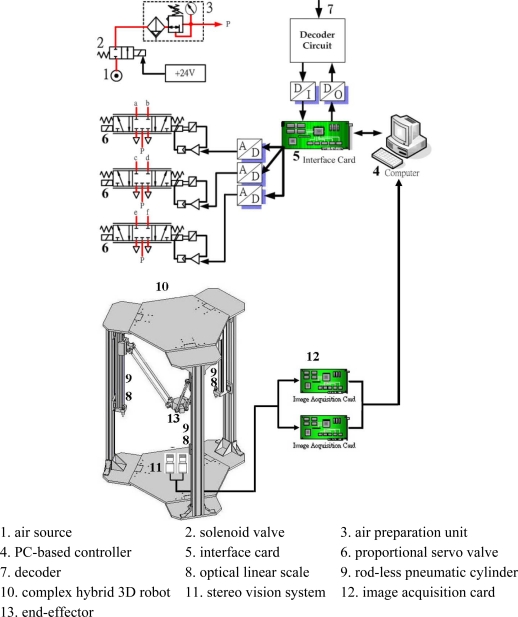
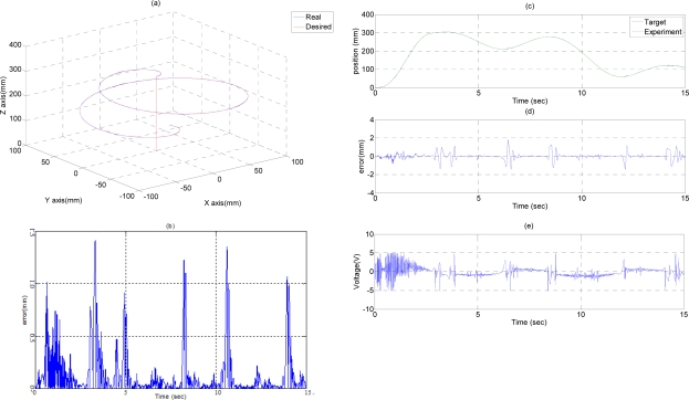
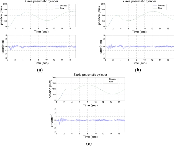
This study aimed to develop a novel 3D parallel mechanism robot driven by three vertical-axial pneumatic actuators with a stereo vision system for path tracking control. The mechanical system and the control system are the primary novel parts for developing a 3D parallel mechanism robot. In the mechanical system, a 3D parallel mechanism robot contains three serial chains, a fixed base, a movable platform and a pneumatic servo system. The parallel mechanism are designed and analyzed first for realizing a 3D motion in the X-Y-Z coordinate system of the robot's end-effector. The inverse kinematics and the forward kinematics of the parallel mechanism robot are investigated by using the Denavit-Hartenberg notation (D-H notation) coordinate system. The pneumatic actuators in the three vertical motion axes are modeled. In the control system, the Fourier series-based adaptive sliding-mode controller with H(∞) tracking performance is used to design the path tracking controllers of the three vertical servo pneumatic actuators for realizing 3D path tracking control of the end-effector. Three optical linear scales are used to measure the position of the three pneumatic actuators. The 3D position of the end-effector is then calculated from the measuring position of the three pneumatic actuators by means of the kinematics. However, the calculated 3D position of the end-effector cannot consider the manufacturing and assembly tolerance of the joints and the parallel mechanism so that errors between the actual position and the calculated 3D position of the end-effector exist. In order to improve this situation, sensor collaboration is developed in this paper. A stereo vision system is used to collaborate with the three position sensors of the pneumatic actuators. The stereo vision system combining two CCD serves to measure the actual 3D position of the end-effector and calibrate the error between the actual and the calculated 3D position of the end-effector. Furthermore, to verify the feasibility of the proposed parallel mechanism robot driven by three vertical pneumatic servo actuators, a full-scale test rig of the proposed parallel mechanism pneumatic robot is set up. Thus, simulations and experiments for different complex 3D motion profiles of the robot end-effector can be successfully achieved. The desired, the actual and the calculated 3D position of the end-effector can be compared in the complex 3D motion control.
Keywords: kinematics analysis; parallel mechanism robot; path tracking control; pneumatic actuator; sensor collaboration; stereo vision.
Figures


References
-
- Brogardh T. Present and future robot control development—An industrial perspective. Ann. Rev. Control. 2007;31:69–79.
-
- Wang J., Liu X.J. Analysis of a novel cylindrical 3-DoF parallel robot. Robot. Auton. Syst. 2003;42:31–46.
-
- Li Q., Wu F.X. Control performance improvement of a parallel robot via the design for control approach. Mechatronics. 2004;14:947–964.
-
- Laribi M.A., Romdhane L., Zeghloul S. Analysis and dimensional synthesis of the DELTA robot for a prescribed workspace. Mech. Mach. Theory. 2007;42:859–870.
-
- Bera T.K., Samantarat A.K., Karmakar R. Robust overwhelming control of a hydraulically driven three-degrees-of-freedom parallel manipulator through a simplified fast inverse model. JSCE. 2009;828:169–184.
Publication types
MeSH terms
LinkOut - more resources
Full Text Sources
Other Literature Sources
