. 2009;9(11):9216-40.
doi: 10.3390/s91109216. Epub 2009 Nov 18.

Thin magnetically soft wires for magnetic microsensors

Affiliations

Thin magnetically soft wires for magnetic microsensors

Valentina Zhukova et al. Sensors (Basel). 2009.

Abstract

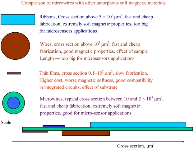
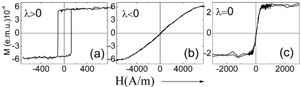
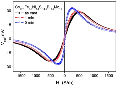
Recent advances in technology involving magnetic materials require development of novel advanced magnetic materials with improved magnetic and magneto-transport properties and with reduced dimensionality. Therefore magnetic materials with outstanding magnetic characteristics and reduced dimensionality have recently gained much attention. Among these magnetic materials a family of thin wires with reduced geometrical dimensions (of order of 1-30 μm in diameter) have gained importance within the last few years. These thin wires combine excellent soft magnetic properties (with coercivities up to 4 A/m) with attractive magneto-transport properties (Giant Magneto-impedance effect, GMI, Giant Magneto-resistance effect, GMR) and an unusual re-magnetization process in positive magnetostriction compositions exhibiting quite fast domain wall propagation. In this paper we overview the magnetic and magneto-transport properties of these microwires that make them suitable for microsensor applications.

Keywords: Barkhausen jump; glass coated microwires; magnetization curves.


Figures

Figure 1.
Figure 1.
Scheme illustrating comparison of microwires with other soft magnetic materials [34].
Figure 2.
Figure 2.
Micrograph of the glass-coated microwire [2].
Figure 3.
Figure 3.
Hysteresis loops of Fe-rich (λs > 0), Co-rich (λs < 0) and Co-Fe-rich s = 0) microwires [38].
Figure 4.
Figure 4.
Hysteresis loops of Co67Fe3.85Ni1.45B11.5Si14.5Mo1.7 microwires with different ρ–ratio [34].
Figure 5.
Figure 5.
Effect of sample geometry (ρ–ratio) on magnetic anisotropy field, Hk [34].
Figure 6.
Figure 6.
(a): v(H) dependence measured for the Fe69Si10B15C6 microwire with the diameter of metallic nucleus, d = 14 μm at different temperatures, T and (b): for the Co68Mn7Si10B15 microwire with d = 8 μm at different applied stress [5,43].
Figure 7.
Figure 7.
(a) v(H) Dependences measured in magnetically bistable Fe75Si12B9C4 microwires and (b) distribution of local nucleation fields Hn measured in the same samples.
Figure 8.
Figure 8.
Z(H) dependence Co67Fe3.85Ni1.45B11.5Si14.5Mo1.7 microwires with different geometry [34].
Figure 9.
Figure 9.
ΔZ/Z(H) dependences measured at (a) f = 30 MHz and I = 1 mA in annealed at 30 mA and (b) at 40 mA of Co67Fe3.85Ni1.45B11.5Si14.5Mo1.7 microwire [34].
Figure 10.
Figure 10.
Excitation current pulse in the wire (a) and voltage induced in the pickup coil (b).
Figure 11.
Figure 11.
Vout(H) of Joule-heated Co67Fe3.85Ni1.45B11.5Si14.5Mo1.7 microwire annealed with 50 mA currents for different time [3].
Figure 12.
Figure 12.
Principle of data storage in wire element. α is the angle between the anisotropy easy axis and the transversal plane.
Figure 13.
Figure 13.
Schematic representation of the encoding system based on magnetic bistability of the microwires [38].
Figure 14.
Figure 14.
Schematic representation of the magnetoelastic sensor based on stress dependence of the switching field [55].
Figure 15.
Figure 15.
Schematic representation of the magnetoelastic pen (a) and two magnetoelastic signatures (b) [55].
Figure 16.
Figure 16.
Schematic representation of the magnetoelastic sensor based on stress dependence of GMI effect (a), ΔZ/Z(H) dependencies of CoMnSiB amorphous microwire measured at different applied stress (b) and calibration curve of sensor (c) [55].
Figure 17.
Figure 17.
Schematic picture showing the working of the temperature sensor based on GMI effect in microwires with low TC [34].
Figure 18.
Figure 18.
Schematic picture showing the working of the temperature sensor based on change of the inductance in microwires with low TC [34].
Figure 19.
Figure 19.
Free-space microwave sensing technique using embedded short ferromagnetic microwires [34].

References

    1. Jiles D.C. Recent advances and future directions in magnetic materials. Acta. Mater. 2003;51:5907–5939.
    1. Zhukov A., González J., Vázquez M., Larin V., Torcunov A. Encyclopedia of Nanoscience and Nanotechnology. Vol. 6. American Scientific Publishers; Valencia, CA, USA: 2004. Nanocrystalline and amorphous magnetic microwires; pp. 365–387.
    1. Zhukov A., Ipatov M., Zhukova V., García C., Gonzalez J., Blanco J.M. Development of ultra-thin glass-coated amorphous microwires for HF magnetic sensor applications. Phys. Stat. Sol. A. 2008;205:1367–1372.
    1. Garcia Prieto M.J., Pina E., Zhukov A.P., Larin V., Marin P., Vázquez M., Hernando A. Glass-coated Co-rich amorphous microwires with enhanced permeability. Sens. Actuat. A. 2000;81:227–231.
    1. Varga R., Zhukov A., Zhukova V., Blanco J.M., Gonzalez J. Supersonic domain wall in magnetic microwires. Phys. Rev. B. 2007;76:132406:1–132406:2.