

Sensing pressure distribution on a lower-limb exoskeleton physical human-machine interface
- PMID: 22346574
- PMCID: PMC3274101
- DOI: 10.3390/s110100207
Sensing pressure distribution on a lower-limb exoskeleton physical human-machine interface
Abstract
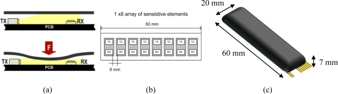
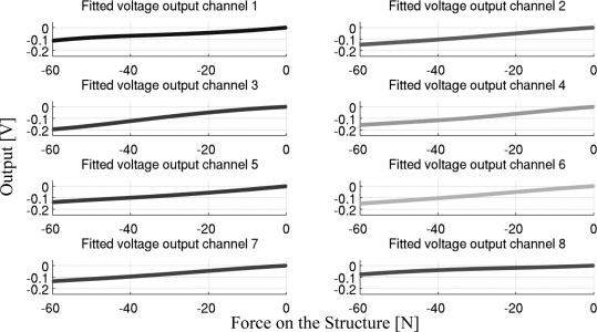
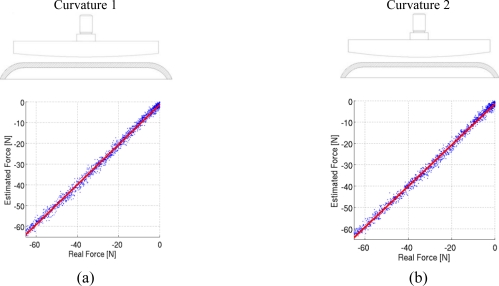
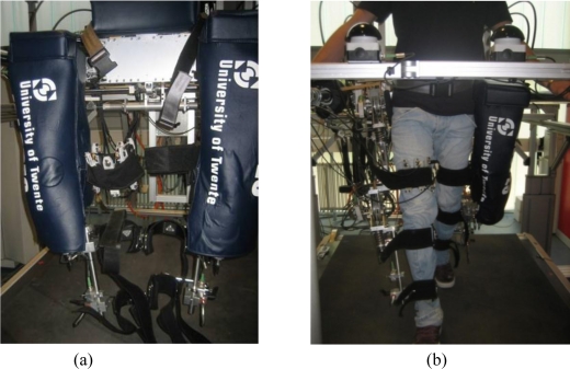
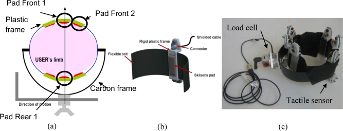
A sensory apparatus to monitor pressure distribution on the physical human-robot interface of lower-limb exoskeletons is presented. We propose a distributed measure of the interaction pressure over the whole contact area between the user and the machine as an alternative measurement method of human-robot interaction. To obtain this measure, an array of newly-developed soft silicone pressure sensors is inserted between the limb and the mechanical interface that connects the robot to the user, in direct contact with the wearer's skin. Compared to state-of-the-art measures, the advantage of this approach is that it allows for a distributed measure of the interaction pressure, which could be useful for the assessment of safety and comfort of human-robot interaction. This paper presents the new sensor and its characterization, and the development of an interaction measurement apparatus, which is applied to a lower-limb rehabilitation robot. The system is calibrated, and an example its use during a prototypical gait training task is presented.
Keywords: distributed force sensor; human-robot interaction; lower-limb exoskeleton; physical human-machine interface.
Figures
References
-
- Guizzo E., Goldstein H. The rise of the body bots. IEEE Spectrum. 2005;42:50–56.
-
- General Electric Co. Hardiman I Prototype Project, Special Interim Study. General Electric Co.; Schenectady, NY, USA: 1968. Report S-68-1060;
-
- Zoss A.B., Kazerooni H., Chu A. Biomechanical design of the Berkeley lower extremity exoskeleton (BLEEX) IEEE ASME Trans. Mechatron. 2006;11:128–138.
-
- Suzuki K., Mito G., Kawamoto H., Hasegawa Y., Sankai Y. Intention-based walking support for paraplegia patients with robot suit HAL. Adv. Robot. 2007;21:1441–1469.
-
- Jezernik S., Colombo G., Keller T., Frueh H., Morari M. Robotic orthosis lokomat: A rehabilitation and research tool. Neuromodulation. 2003;6:108–115. - PubMed
Publication types
MeSH terms
Substances
LinkOut - more resources
Full Text Sources
Other Literature Sources
