

Brillouin corrosion expansion sensors for steel reinforced concrete structures using a fiber optic coil winding method
- PMID: 22346672
- PMCID: PMC3274314
- DOI: 10.3390/s111110798
Brillouin corrosion expansion sensors for steel reinforced concrete structures using a fiber optic coil winding method
Abstract
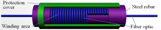
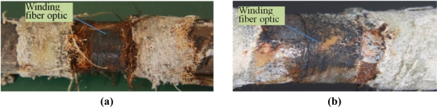
In this paper, a novel kind of method to monitor corrosion expansion of steel rebars in steel reinforced concrete structures named fiber optic coil winding method is proposed, discussed and tested. It is based on the fiber optical Brillouin sensing technique. Firstly, a strain calibration experiment is designed and conducted to obtain the strain coefficient of single mode fiber optics. Results have shown that there is a good linear relationship between Brillouin frequency and applied strain. Then, three kinds of novel fiber optical Brillouin corrosion expansion sensors with different fiber optic coil winding packaging schemes are designed. Sensors were embedded into concrete specimens to monitor expansion strain caused by steel rebar corrosion, and their performance was studied in a designed electrochemical corrosion acceleration experiment. Experimental results have shown that expansion strain along the fiber optic coil winding area can be detected and measured by the three kinds of sensors with different measurement range during development the corrosion. With the assumption of uniform corrosion, diameters of corrosion steel rebars were obtained using calculated average strains. A maximum expansion strain of 6,738 με was monitored. Furthermore, the uniform corrosion analysis model was established and the evaluation formula to evaluate mass loss rate of steel rebar under a given corrosion rust expansion rate was derived. The research has shown that three kinds of Brillouin sensors can be used to monitor the steel rebar corrosion expansion of reinforced concrete structures with good sensitivity, accuracy and monitoring range, and can be applied to monitor different levels of corrosion. By means of this kind of monitoring technique, quantitative corrosion expansion monitoring can be carried out, with the virtues of long durability, real-time monitoring and quasi-distribution monitoring.
Keywords: Brillouin sensor; corrosion sensor; fiber optic; fiber optic coil; steel reinforced concrete structure; structural health monitoring.
Figures


References
-
- Bentur S., Diamond N.S. Berke, Steel Corrosion in Concrete: Fundamentals and Civil Engineering Practice. E & FN Spon; London, UK: 1997.
-
- Broomfield J.P. Corrosion of Steel in Concrete. E & FN Spon; London, UK: 1997.
-
- Gonzalez J.A., Feliu S., Rodriguez P. Threshold steel corrosion rates for durability problems in reinforced structures. J. Corros. 1997;53:65–71.
-
- Schiessl P. Corrosion of Steel in Concrete, RILEM Technical Committe 60-CSC. Chapman & Hall; New York, NY, USA: 1988.
-
- Schutze M., editor. Corrosion and Environmental Degradation. II. Wiley-VCH; Weinheim, Germany: 2000. Elsener Corrosion of Steel in Concrete; pp. 389–436.
Publication types
LinkOut - more resources
Full Text Sources
