. 2012 Feb;176(3-4):345-358.
doi: 10.1007/s00604-011-0727-8. Epub 2011 Nov 4.

Characterization of CdSe nanocrystals coated with amphiphiles. A capillary electrophoresis study

Characterization of CdSe nanocrystals coated with amphiphiles. A capillary electrophoresis study

Sławomir Oszwałdowski et al. Mikrochim Acta. 2012 Feb.

Abstract

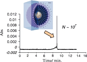
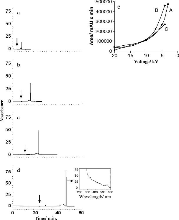
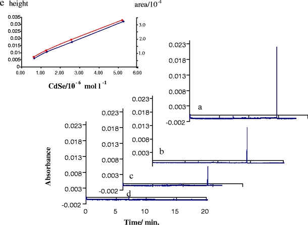
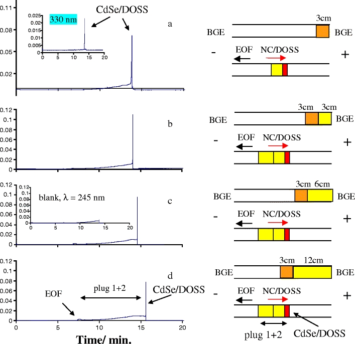
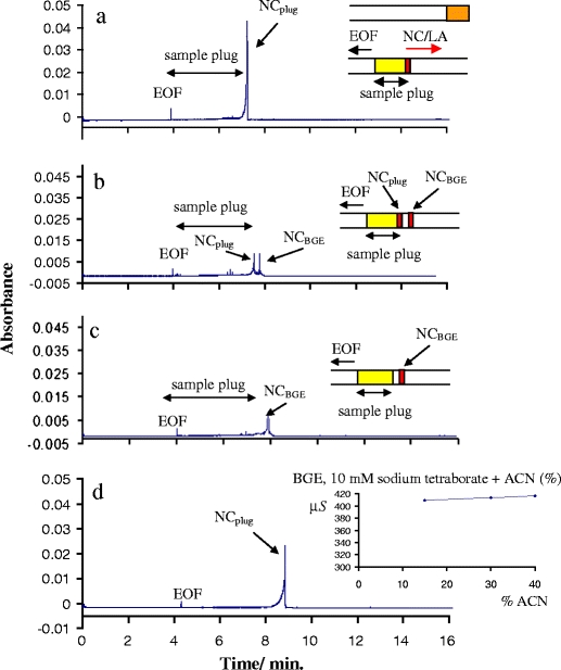
We have synthesized CdSe nanocrystals (NCs) possessing a trioctylphosphine surface passivation layer and modified with amphiphilic molecules to form a surface bilayer. The NCs covered with single amphiphiles are not stable in aqueous solution, but a mixed amphiphilic system is shown to provide stability in solution over several months. The solutions of the modified NCs were characterized by UV-Vis absorbance, photoluminescence, and transmission electron microscopy. An electrophoretic study revealed two operational modes. The first relies on the enrichment of NCs using a micellar plug as a tool. The accumulation of NCs at the plug-electrolyte buffer interface results in a sharp peak. By controlling the electrophoretic conditions, nanocrystals were forced to exit a micellar plug into an electrolyte buffer. We conclude that a system consisting of modified nanocrystals and a micellar plug can act as a mixed pseudomicellar system, where modified nanocrystals play the role of pseudomicelles.FigureElectrophoretic focusing of amphiphile coated CdSe nanocrystals using a micellar plug. ELECTRONIC SUPPLEMENTARY MATERIAL: The online version of this article (doi:10.1007/s00604-011-0727-8) contains supplementary material, which is available to authorized users.


Figures

Figure
Figure
Electrophoretic focusing of amphiphile coated CdSe nanocrystals using a micellar plug.
Fig. 1
Fig. 1
Dispersion of CdSe NCs in aqueous solution of sodium oleate
Fig. 2
Fig. 2
Upper (a, b). Spectra for CdSe NCs due to solubilization of CdSe/TOP NCs (2.4 nm, first excition band, λ = 508 nm) using a non-ionic or a pair of ionic/non-ionic surfactants. a, UV-Vis spectra, b, photoluminescence spectra (PL). Samples of CdSe NCs: A, in chloroform, B, dissolved in TX-100 and C, in mixture of TX-100/CTAB. As an insert in (b) is comparison of the normalized emission efficacy (PL per 0.1 AU) reflecting the PL effect, due to NCs solubilization in these surfactants. Below (c, d). Coating and emission efficacy due to solubilization of CdSe/TOP NC in selected pairs of amphiphilic surfactants. Data summarized for CdSe NCs sizes = 2.7–3.3 nm. Figures: c, coating efficacy in the form of absorbance of the NCs solution (first exciton band of NC in UV-Vis); d, the normalized emission efficacy (PL per 0.1 AU) for NCs solutions according to frame c. Abbreviations: CdSe, chloroform solution of CdSe (50 μl of 2–5 10−6 M CdSe NCs per 500–300 μl of chloroform). Coating with: only non-ionic surfactants (TX-100, N-100; 10% w:w) (examples of coating with single amphiphile) and pairs of surfactants: 10% TX-100 (w:w) containing 100 mM of ionic surfactants: (anionic) SDS sodium dodecyl sulphate; DOSS, dioctyl sulfosuccinate; (cationic) CTAB, cetyltrimethylammonium bromide; CP, 1-dodecylpyridinium chloride. Sample preparation: (50 μl of 2–5 10−6 mol l−1 CdSe/TOP NCs per 300 μl of surfactant solution). An example of CdSe/TOP being solubilized in a pair of non-ionic surfactant/polymer (TX-100/PVP; 0.5 g 10% TX-100 and 0.022 g PVP) is shown for comparison
Fig. 3
Fig. 3
Effect of a kind of an anionic amphiphile in the sample plug on the formation of a focussed peak for CdSe/TOP//N-101 NCs. Sample: CdSe/TOP NCs, size 3.6 nm, dispersed in non-ionic amphiphile N-101 (10%). Injection: a, only sample of CdSe/TOP//N-101 NCs/10% N-101 (w/w); b, sample of CdSe/TOP//N-101 NCs containing N-101 5% (w/w)/0.28 M C5H11SO3Na; c, sample of CdSe/TOP//N-101 NCs containing N-101 5% (w/w)/0.22 M C12H25SO3Na. Conditions: electrolyte buffer, 10 mM sodium tetraborate; voltage, 25 kV; injection 50 mbar/0.1 min; detection 330 nm. Inset, frame a, shows spectra for non-ionic N-101 and CdSe/TOP//N-101, respectively. The vertical arrow shows the detection wavelength selective for NCs, applied to CE experiment
Fig. 4
Fig. 4
Focusing of CdSe/TOP//SDS NCs due to migration of NCs within a micellar plug and characteristic of the peaks for CdSe coated with a pair of TX-100/SDS or TX-100/DOSS amphiphiles. Figs. a-d, visualization of focused peaks for CdSe/TOP//SDS NCs, core size 2.9 nm. Voltage applied: a, 20 kV; b, 14 kV; c, 10 kV and d, 4 kV. Injection: 35 mbar/5 s. Sample preparation: CdSe/TOP NCs dispersed in 0.5 g 10% TX-100 with 0.032 g SDS. Electrolyte buffer: 5 mM sodium tetraborate. Positions of EOF were denoted by vertical arrows. As an inset, frame d is DAD spectrum for CdSe/TOP//SDS NCs obtained during a CE run. Frame e, peak area dependence on applied voltage. Electrolyte buffer: 5 mM (A, C) and 3 mM (B) sodium tetraborate
Fig. 5
Fig. 5
Two plugs system. Impact of the concentration of an ionic amphiphile (DOSS) in the first plug on peak shape of CdSe/DOSS NCs. Frames (left side): a, two plugs system with the first plug containing 10% TX-100 (w:w), 0.148 mol l−1 DOSS and 5.2 × 10−6 mol l−1 CdSe NCs; b, the same system, first plug: 10% TX-100, 0.074 mol l−1 DOSS and 2.6 × 10−6 mol l−1 CdSe NCs; c, ibidem, 10% TX-100, 0.037 mol l−1 DOSS and 1.3 × 10−6 mol l−1 CdSe NCs; d, two plugs system with first plug: 10% TX-100 and 0.148 mol l−1 DOSS (blank). As the second plug, a pair of amphiphiles 10% (w:w) TX-100, 0.148 mol l−1 DOSS, were applied for (a-d). Conditions: BGE 10 mM sodium tetraborate, applied voltage 20 kV, detection UV-vis λ = 330 nm, selective for CdSe NCs (NC size, 3.6 nm). Length of a plug: first 3.3 cm, second 6.4 cm. Right side. Frame (e), the relation between peak area (red line) or height (blue line) and cCdSe
Fig. 6
Fig. 6
Comparison of one and two plug systems, as well as impact of the length of the second plug on migration and peak shape of CdSe/DOSS NCs. Frames: a, one plug system (CdSe NCs, size 3.6 nm, dispersed in TX-100/DOSS); b, two plugs system with 3.3 cm second plug; c, two plugs system with 6.4 cm second plug and d, two plug system with 11.7 cm second plug. As the first plug the CdSe NCs dispersed in a pair of surfactants (0.6 g 10% (w:w) TX-100/0.148 mol l−1 DOSS) was applied through frames a-d, plug length 3.3 cm. As the second plug a pair of surfactants (0.6 g 10% (w:w) TX-100/ 0.148 mol l−1 DOSS) with various lengths (3.3, 6.4 and 11.7 cm, respectively) was applied. Conditions: cCdSe = 5.2 × 10−6 mol l−1 (first plug), BGE 10 mM sodium tetraborate, applied voltage 20 kV, detection UV-vis 245 nm (inset frame a, λ = 330 nm to monitor NCs only). Inset frame c, the two plugs system, without NCs (blank). Right side are graphic interpretations of each run, where upper is the starting situation and below is the situation observed at detector (orange, first plug; yellow, second plug and red, NCs). Note, that due to the NCs transport from the first plug to the plug/BGE boundary, both plugs (1 + 2) are TX-100/DOSS layers free from NCs, denoted as yellow
Fig. 7
Fig. 7
Effect of modification of BGE or plug by acetonitrile (ACN). A sample used as a plug was CdSe NCs dispersed in TX-100/sodium laurate (LA) (10% w:w/0.13 M). Frames: a, BGE 10 mM sodium tetraborate; b, BGE 10 mM sodium tetraborate containing 15% ACN; c, BGE 10 mM sodium tetraborate containing 30% ACN. Frame d, modification of a plug by ACN (1:1); BGE, 10 mM sodium tetraborate. Peaks: NCplug, CdSe NCs being in a plug; NCBGE, CdSe NCs released from a plug to BGE. Conditions: voltage 20 kV, detection UV-vis 330 nm in order to visualize NCs only, injection 50 mbar/0.1 min. Each frame was set at the same absorbance scale in order to visualize the effect

Similar articles

Cited by

References

    1. Somers RC, Bawendi MG, Nocera DG. CdSe nanocrystal based chem-/bio- sensors. Chem Soc Rev. 2007;36:579–591. doi: 10.1039/b517613c. - DOI - PubMed
    1. Yu WW, Qu L, Guo W, Peng X. Experimental determination of the extinction coefficient of CdTe, CdSe, and CdS nanocrystals. Chem Mater. 2003;15:2854–2860. doi: 10.1021/cm034081k. - DOI
    1. Sergeev GB. Nanochemistry. Amsterdam: Elsevier B.V; 2006.
    1. Pons T, Uyeda HT, Medintz IL, Mattoussi H. Hydrodynamic dimensions, electrophoretic mobility, and stability of hydrophilic quantum dots. J Phys Chem B. 2006;110:20308–20316. doi: 10.1021/jp065041h. - DOI - PubMed
    1. Radko SP, Chrambach A. Separation and characterization of sub-μm- and μm-sized particles by capillary zone electrophoresis. Electrophoresis. 2002;23:1957–1972. doi: 10.1002/1522-2683(200207)23:13<1957::AID-ELPS1957>3.0.CO;2-I. - DOI - PubMed

LinkOut - more resources