. 2010 Nov;1(5-6):349-359.
doi: 10.1007/s13244-010-0047-2. Epub 2010 Oct 21.

Technical aspects of CT imaging of the spine

Affiliations

Technical aspects of CT imaging of the spine

Bernhard Tins. Insights Imaging. 2010 Nov.

Abstract

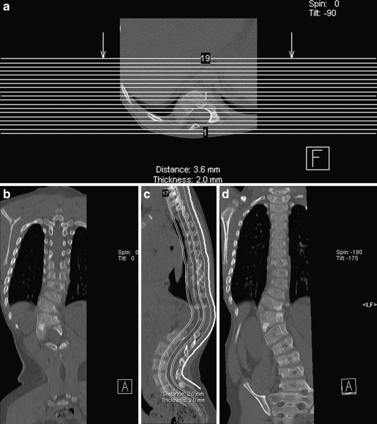
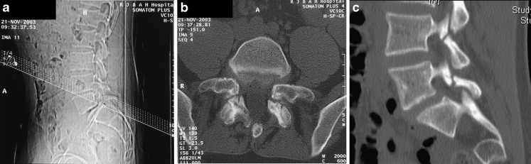
This review article discusses technical aspects of computed tomography (CT) imaging of the spine. Patient positioning, and its influence on image quality and movement artefact, is discussed. Particular emphasis is placed on the choice of scan parameters and their relation to image quality and radiation burden to the patient. Strategies to reduce radiation burden and artefact from metal implants are outlined. Data acquisition, processing, image display and steps to reduce artefact are reviewed. CT imaging of the spine is put into context with other imaging modalities for specific clinical indications or problems. This review aims to review underlying principles for image acquisition and to provide a rough guide for clinical problems without being prescriptive. Individual practice will always vary and reflect differences in local experience, technical provisions and clinical requirements.


Figures

Fig. 1
Fig. 1
Flexion (a) and extension (b) CT in a patient with a dens fracture. Radiographs were inconclusive, CT allows for fast and accurate assessment of bone alignment at the endpoints of flexion and extension
Fig. 2
Fig. 2
ac An 11-year-old girl with torticollis since a trampolining accident. CT was performed to exclude a fixed rotation anomaly. CT with the patient’s head turned to the left (a), in neutral position (b) and turned to the right (c) demonstrates free movement in the atlantoaxial joint. The examination was performed in low-dose technique, kVp 100, reference mAs 50. Despite these low settings, the examination results in good image quality. CT is not well-suited for true dynamic imaging, but “snapshot” imaging at various stages of a continuous movement is possible
Fig. 3
Fig. 3
A patient with a healed atlas fracture, demonstrating the influence of the reconstruction and reformatting parameters on the image quality. A reconstruction thickness of 3 mm in the axial plane results in good image quality in the axial plane (3-mm thickness); however, reformatting in 3-mm thickness in the sagittal and coronal plane results in poor image quality. After reconstruction in 1-mm thickness and reformatting in 3-mm thickness in all three planes, there is a much better image quality in the sagittal and coronal plane. When reformatting the images in 1-mm thickness, the spatial resolution is increased best appreciated on the coronal image in the occipitoatlantal articulation. The images are also much noisier than after reformatting in 3-mm thickness. The images should always be reconstructed in relatively thin slice thickness. Reformatting in thicker slices then still results in good quality images
Fig. 4
Fig. 4
ac A patient with an accessory facet joint ossicle. In the axial plane this is easily seen using a bone algorithm and bone windows for display (a). Using a soft tissue algorithm for reconstruction and bone windows for display, the lesion is hard to visualise (b). Using a soft tissue reconstruction algorithm and soft tissue windows for display, the lesion is invisible (c). Images should routinely be reconstructed with a sharp (for bone and lung) and soft (for soft tissues) algorithm and be displayed with appropriate window settings
Fig. 5
Fig. 5
ad A patient with scoliosis due to developmental anomalies in the thoracolumbar junction. On conventional coronal reformats the vertebral morphology and alignment is not easily assessed (a, b). Curved coronal reformats (c, d) have been chosen to “remove” kyphosis and lordosis, the spine is projected onto a curved plane, making it easier to assess the scoliosis and morphology
Fig. 6
Fig. 6
a, bA patient with foraminal narrowing due to disc bulging especially on the right (a). Narrowing of the window width compared with normal soft tissue windows results in improved visualisation of the foraminal narrowing on sagittal reformats (b)
Fig. 7
Fig. 7
ac A patient with a notochordal rest. On conventional bone window settings (a) (bone algorithm) the sclerosis is only faintly visible. On soft tissue window settings (b) (soft tissue algorithm) the lesion is better visualised. The best visualisation is achieved with individually adjusted narrow window settings (c)
Fig. 8
Fig. 8
a, b Patient with ankylosing spondylitis run over by a car. CT not only demonstrates the grossly displaced overriding spinal fracture (a) but also the impingement of cardiovascular structures by the spine fracture (b). CT is superior to MRI in ease and speed of examination in trauma cases
Fig. 9
Fig. 9
ac CT for the assessment of spondylolysis: for the reverse gantry technique as performed on single slice scanners the imaging plane is chosen in the plane of the posterior elements (a). The high in plane resolution allows for good assessment of bony continuity (b). However once the gantry is tilted spiral acquisition is no longer possible. This technique is obsolete for MD-CT where real-time 3D reformatting allows to chose the image plane to optimally display the lesion, in this case spondylolysis of L4 and L5 (c)
Fig. 10
Fig. 10
CT of the spine can often accurately depict disc disease and neural compromise. Especially the presence of epidural fat can help depict disc disease
Fig. 11
Fig. 11
ag Metal implants in the spine are frequently made of titanium. This does usually allow for satisfactory MRI. However, if ferrous metals or multiple implants are used MRI can become non-diagnostic. CT is usually still able to provide diagnostic images. In this example, two posterior and one lateral rod with corresponding anchoring screws have been used (a). Above the level of the lateral rod MRI results in diagnostic images (b), at the level of the lateral rod the artefact becomes too marked (c). CT imaging allows for excellent visualisation of the spine and implants and demonstrates misplacement of several pedicle screws (d, e). The coronal reformat in particular allows for a quick and accurate assessment of screw misplacement. Volume rendering allows for easy visualisation of implant placement in relation to the spine (f, g)
Fig. 12
Fig. 12
a, b Patient who had previously undergone disc replacement at C4/5 and fusion at C5/6. Lateral radiographs show a radiolucent zone in C4 vertebra adjacent to the disc implant (a). This is not visualised on CT (b). The depiction of bony lysis adjacent to metal implants can be difficult. If lysis is seen in either CT imaging or radiographs this is likely to be a true finding

References

    1. McCollough CH, Bruesewitz MR, Kofler JM., Jr CT dose reduction and dose management tools: overview of available options. Radiographics. 2006;26(2):503–512. doi: 10.1148/rg.262055138. - DOI - PubMed
    1. Biswas D, Bible JE, Bohan M, et al. Radiation exposure from musculoskeletal computerized tomographic scans. J Bone Joint Surg Am. 2009;91(8):1882–1889. doi: 10.2106/JBJS.H.01199. - DOI - PubMed
    1. Richards PJ, George J. Diagnostic CT radiation and cancer induction. Skeletal Radiol. 2009;39(5):421–424. doi: 10.1007/s00256-009-0819-2. - DOI - PubMed
    1. Richards PJ, George J, Metelko M, et al. Spine computed tomography doses and cancer induction. Spine (Phila Pa 1976) 2010;35(4):430–433. - PubMed
    1. McCollough CH, Christner JA, Kofler JM. How effective is effective dose as a predictor of radiation risk? AJR Am J Roentgenol. 2010;194(4):890–896. doi: 10.2214/AJR.09.4179. - DOI - PubMed

LinkOut - more resources