Review
. 2012 May;123(5):858-82.
doi: 10.1016/j.clinph.2012.01.010. Epub 2012 Feb 19.

A practical guide to diagnostic transcranial magnetic stimulation: report of an IFCN committee

Affiliations
Review

A practical guide to diagnostic transcranial magnetic stimulation: report of an IFCN committee

S Groppa et al. Clin Neurophysiol. 2012 May.

Abstract

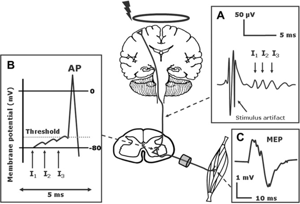
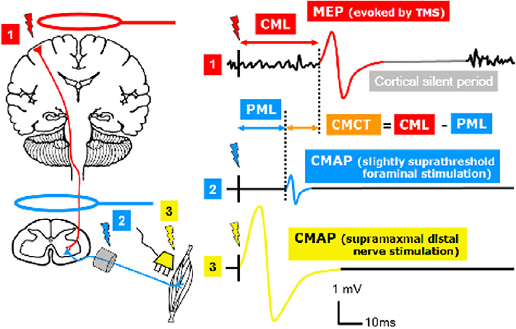
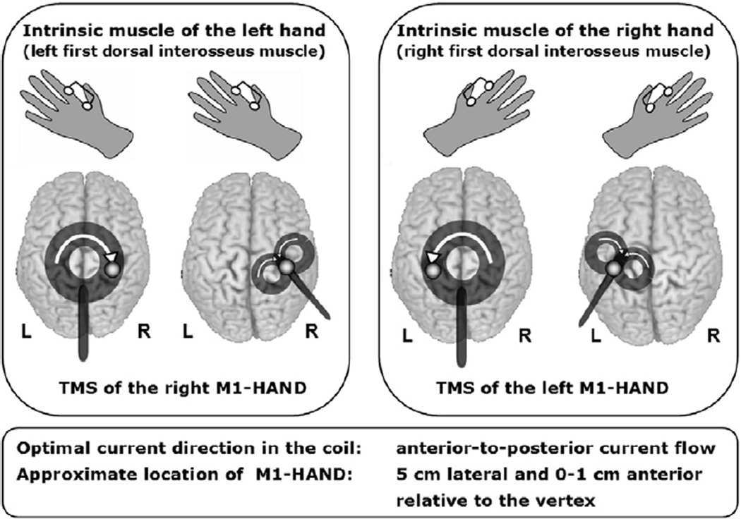
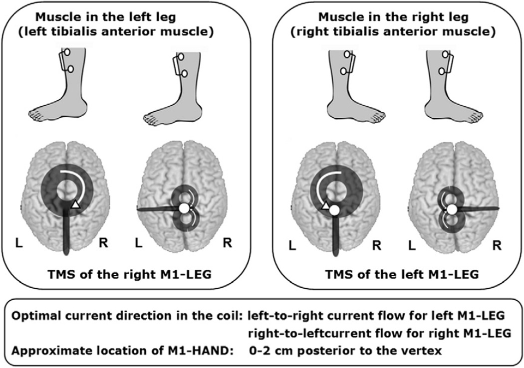
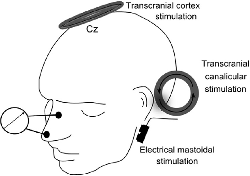
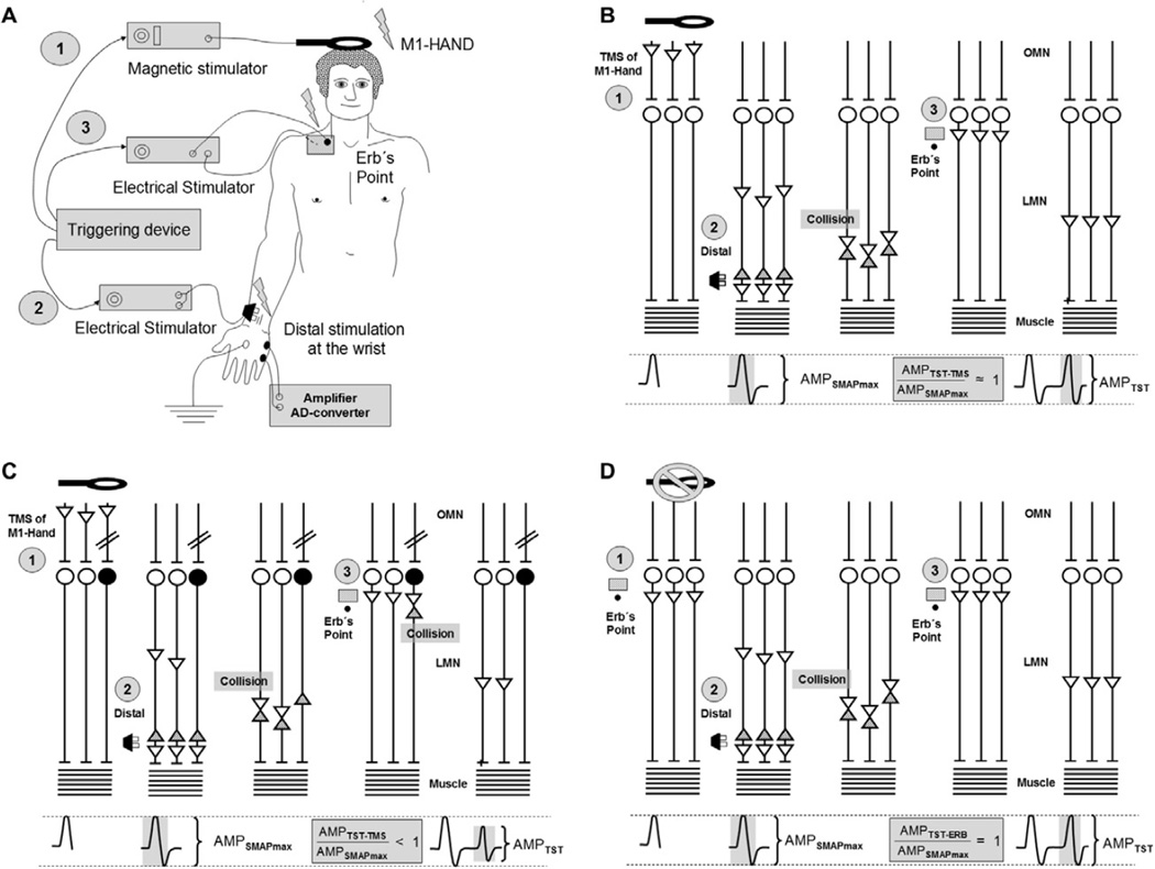
Transcranial magnetic stimulation (TMS) is an established neurophysiological tool to examine the integrity of the fast-conducting corticomotor pathways in a wide range of diseases associated with motor dysfunction. This includes but is not limited to patients with multiple sclerosis, amyotrophic lateral sclerosis, stroke, movement disorders, disorders affecting the spinal cord, facial and other cranial nerves. These guidelines cover practical aspects of TMS in a clinical setting. We first discuss the technical and physiological aspects of TMS that are relevant for the diagnostic use of TMS. We then lay out the general principles that apply to a standardized clinical examination of the fast-conducting corticomotor pathways with single-pulse TMS. This is followed by a detailed description of how to examine corticomotor conduction to the hand, leg, trunk and facial muscles in patients. Additional sections cover safety issues, the triple stimulation technique, and neuropediatric aspects of TMS.


Figures

Fig. 1
Fig. 1
Neurophysiological basis of the motor evoked potential (MEP). (A) TMS-induced activation of the corticospinal neurons with a predominant contribution by late Indirect waves (I waves). and (B) Temporo-spatial summation at the cortico-motoneuronal synapses (C) Motor evoked potential (modified from: Siebner HR, Ziemann U. Das TMS-Buch, Heidelberg: Springer Medizin Verlag, 2007, with kind permission of Springer Medizin Verlag).
Fig. 2
Fig. 2
Schematic representation of the investigative steps to assess the corticomotor conduction. The order of peripheral and transcranial neurostimulation can be interchanged according to the preferences of the examiner. CMAP: compound motor action potential; MEP: motor evoked potential, CMT: cortical motor threshold.
Fig. 3
Fig. 3
Schematic illustration of the motor responses elicited with TMS of the M1 (1), foraminal electromagnetic stimulation (2), and supramaximal distal nerve stimulation (3). CMAP: Compound motor action potential; MEP: motor evoked potential (note that the MEP is also a CMAP but transcranially evoked), PML: peripheral motor latency (conduction time from neuroforamen to muscle), CML: cortical motor latency (conduction time from cortex to muscle), CMCT: central motor conduction time (calculated as difference between CML and PML). Note that this method of CMCT estimation includes the very proximal peripheral conduction time until the neuroforamen.
Fig. 4
Fig. 4
Schematic illustration of peripheral motor latency (PML) calculation: (A) electric or magnetic stimulation of the proximal spinal nerve at the level of intervertebral foramen and (B) F-wave method. The studied nerve is electrically stimulated at the vicinity of the studied muscle. The orthodromic response (M-Wave) precedes the antidromic response of the spinal motoneurons (F-wave). F corresponds to the shortest F-wave latency and M equals the distal motor latency. One millisecond is subtracted to account for a central delay at the cell body of the motoneuron (modified from: Siebner HR, Ziemann U. Das TMS-Buch, Heidelberg: Springer Medizin Verlag, 2007, with kind permission of Springer Medizin Verlag).
Fig. 5
Fig. 5
Transcranial stimulation of corticospinal paths to the distal upper extremities, with the round respectively figure-of-eight coil. Point on the coil ring: optimal stimulation spot of the primary motor hand area to the right (A) or left (B), Arrows: technical direction of current flow in the coil. For optimal stimulation of the right motor hand area (derivative of the MEP of an intrinsic muscle of the left hand) should be the direction of current in the coil as seen from above shown clockwise. For the stimulation of the left motor hand area (derivative of the MEP of an intrinsic muscle of the right hand) is made with the round stimulation coil, the technical current flow in the coil is oriented counter-clockwise seen from above. As a starting point in the derivation of hand muscles the coils can be positioned so that the stimulating coil is over the M1, approximately 0–1 cm anterior and about 4–5 cm lateral from the vertex (modified from: (Groppa et al., 2010), with kind permission of Georg Thieme Verlag).
Fig. 6
Fig. 6
Transcranial stimulation of corticospinal paths to the distal lower extremities with the circular and figure-of-eight coil respectively. Point on the coil ring: optimal stimulation spot of the primary motor leg area right (A) or left (B), Arrows: technical direction of current flow in the coil. For stimulation of right hemisphere leg area (derivation of MEP from a leg or foot muscle of the left leg), the current direction proceeds is in the coil portion, which rests on the leg area, from right to left. For stimulation of the left hemisphere leg area (derivation of MEP from a leg or foot muscle of the left leg), the current direction proceeds in the coil portion, which rests on the leg area, from left to right. The coil center is about 5–6 cm in front of the vertex and the coil whorls of the posterior coil portion lie about 1–2 cm behind the vertex over the primary motor leg area on the skull (modified from: (Groppa et al., 2010), with kind permission of Georg Thieme Verlag).
Fig. 7
Fig. 7
Schematic illustration of the facial nerve diagnostic with transcranial M1 stimulation with the round coil; extra-axial canalicular magnetic stimulation as well as supramaximal electrical stimulation at stylomastoid foramen.
Fig. 8
Fig. 8
Schematic representation of the triple pulse stimulation (TST). (A) Experimental setup with three stimulation devices that are triggered at a defined temporal pattern by a synchronization device. A transcranial magnetic stimulation of the M1-Hand (1) is followed by an electric supramaximal stimulation of the distal peripheral nerve (2) and supramaximal stimulation at the Erb’s point at the proximal nerve pathway (3). (B) Schematic representation of the stimulation of different segments of the pathway in normal subjects. (C) Altered propagation of action potentials in peripheral nerves and the motor response induced by TST in the presence of a partial corticospinal block. (D) Peripheral stimulation with initial stimulation over the Erb’s point instead of the TMS of the contralateral hand area. Amplitude (AMP) of MEP from the intrinsic hand muscles. UMN = upper (corticospinal) motoneuron, LMN = lower (peripheral) motoneuron. AMPTST Amplitude after TST (modified from: Siebner HR, Ziemann U. Das TMS-Buch, Heidelberg: Springer Medizin Verlag, 2007, with kind permission of Springer Medizin Verlag).

Comment in

References

    1. Adrian ED, Moruzzi G. Impulses in the pyramidal tract. J Physiol. 1939;97:153–199. - PMC - PubMed
    1. Amassian VE, Stewart M, Quirk GJ, Rosenthal JL. Physiological basis of motor effects of a transient stimulus to cerebral cortex. Neurosurgery. 1987;20:74–93. - PubMed
    1. Awiszus F. TMS and threshold hunting. Suppl Clin Neurophysiol. 2003;56:13–23. - PubMed
    1. Awiszus F. Fast estimation of transcranial magnetic stimulation motor threshold: is it safe? Brain Stimul. 2011;4:58–59. - PubMed
    1. Awiszus F, Feistner H. Kortikale Reizschwelle. Das TMS-Buch. 2007:149–158.

MeSH terms