. 2012 Jan;17(1):015001.
doi: 10.1117/1.JBO.17.1.015001.

High-throughput optofluidic system for the laser microsurgery of oocytes

Affiliations

High-throughput optofluidic system for the laser microsurgery of oocytes

Charlie Chandsawangbhuwana et al. J Biomed Opt. 2012 Jan.

Abstract

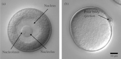
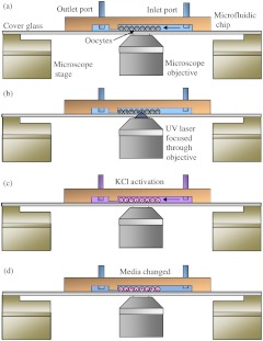
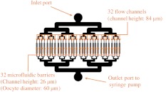
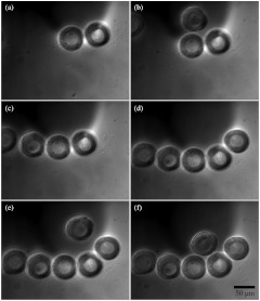
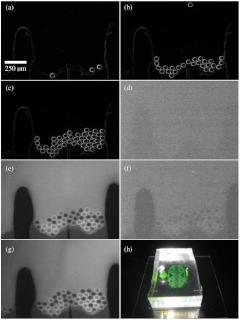
This study combines microfluidics with optical microablation in a microscopy system that allows for high-throughput manipulation of oocytes, automated media exchange, and long-term oocyte observation. The microfluidic component of the system transports oocytes from an inlet port into multiple flow channels. Within each channel, oocytes are confined against a microfluidic barrier using a steady fluid flow provided by an external computer-controlled syringe pump. This allows for easy media replacement without disturbing the oocyte location. The microfluidic and optical-laser microbeam ablation capabilities of the system were validated using surf clam (Spisula solidissima) oocytes that were immobilized in order to permit ablation of the 5 μm diameter nucleolinus within the oocyte nucleolus. Oocytes were the followed and assayed for polar body ejection.


Figures

Fig. 1
Fig. 1
(a) An unactivated surf clam (Spisula solidissima) oocyte viewed under differential interference contrast (DIC). The nucleolinus is an intra-nuclear organelle that has a suspected role in regulating meiotic cell division. The diameter of nucleolinus is approximately 5 µm and the oocyte is approximately 60 µm. (b) A surf clam oocyte 30 min post-activation viewed under DIC. After activation, the nucleus breaks down and a polar body is ejected from the side of the cell, a sign of the first meiotic division.
Fig. 2
Fig. 2
Side cross-sectional view of the microfluidic chamber (not drawn to scale). (a) Small quantities of oocytes are introduced into the inlet port and a syringe pump pulls the oocytes into the channels. The channel height is 86 µm, which allows for 60 µm diameter oocytes to flow through. Oocytes are stopped by a physical barrier that only allows filtered sea water to flow through a 26 µm high channel to the outlet port. (b) Oocytes are irradiated using a focused 337 nm UV beam. (c) 14% KCl/filtered sea water is perfused through the channel to activate the oocytes. (d) Fresh media is continuously changed using the syringe pump. Cells are checked for polar body ejections after 50 min.
Fig. 3
Fig. 3
Top view of the microfluidic chamber. Oocytes enter through the inlet port and are pulled through the chamber by a syringe pump connected to the outlet port. The oocytes then flow into 32 individual channels. In each channel, there is a microfluidic barrier that traps the cells. Oocytes in each channel can be subjected to one of three different experimental conditions: no ablation, nucleolinus ablation, or nucleolus ablation. By having separate channels, an oocyte’s location and experimental condition can be recovered easily by recording its channel number.
Fig. 4
Fig. 4
One channel being loaded with oocytes under 40× DIC. Oocytes are loaded into the inlet port and flow towards the channels (not shown). Once in the channels, the oocytes are blocked by the microfluidic barrier (flow is from the top to the bottom of the images). Image series is taken over 30 sec.
Fig. 5
Fig. 5
Prototype testing of the microfluidic chamber. (a–c) 59.1  μm±0.9  μm beads were loaded under phase contrast into the microfluidic chamber. Beads were blocked by the microfluidic barrier. (d) Switching to fluorescence imaging showed no fluorescence. (e) Fluorescein was flowed through channel. Beads appeared apparent in contrast to the background fluorescence. (f) Background fluorescence was washed out with distilled water. (g) Fluorescein was reintroduced into channel. (h) Image of final microfluidic chamber with fluorescein inside channels. The fluidic connections to the syringe pump are not shown.

Similar articles

Cited by

References

    1. Palermo G., et al. , “Pregnancies after intracytoplasmic injection of single spermatozoon into an oocyte,” The Lancet 340(8810), 17–18 (1992).LOANBN10.1016/0140-6736(92)92425-F - DOI - PubMed
    1. Kimura Y., Yanagimachi R., “Intracytoplasmic sperm injection in the mouse,” Biol. Reprod. 52(4), 709–720 (1995).BIREBV10.1095/biolreprod52.4.709 - DOI - PubMed
    1. Kinsey W. H., “Analysis of signaling pathways in zebrafish development by microinjection,” Methods Mol. Biol. 518, 67–76 (2009).MMBYBO10.1007/978-1-59745-202-1_6 - DOI - PMC - PubMed
    1. Tengowski M. W., Schatten H., “Microscopic techniques for studying sperm–oocyte interaction during fertilization and early embryonic development,” Methods Mol. Biol. 1, 165–199 (2004).MMBYBO10.1385/1-59259-744-0:165 - DOI - PubMed
    1. Duffy D. C., et al. , “Rapid prototyping of microfluidic systems in poly(dimethylsiloxane),” Anal. Chem. 70(23), 4974–4984 (1998).ANCHAM10.1021/ac980656z - DOI - PubMed

Publication types

MeSH terms