. 2012 May;220(5):504-13.
doi: 10.1111/j.1469-7580.2012.01486.x. Epub 2012 Feb 23.

Study of the three-dimensional orientation of the labrum: its relations with the osseous acetabular rim

Affiliations

Study of the three-dimensional orientation of the labrum: its relations with the osseous acetabular rim

Noémie Bonneau et al. J Anat. 2012 May.

Abstract

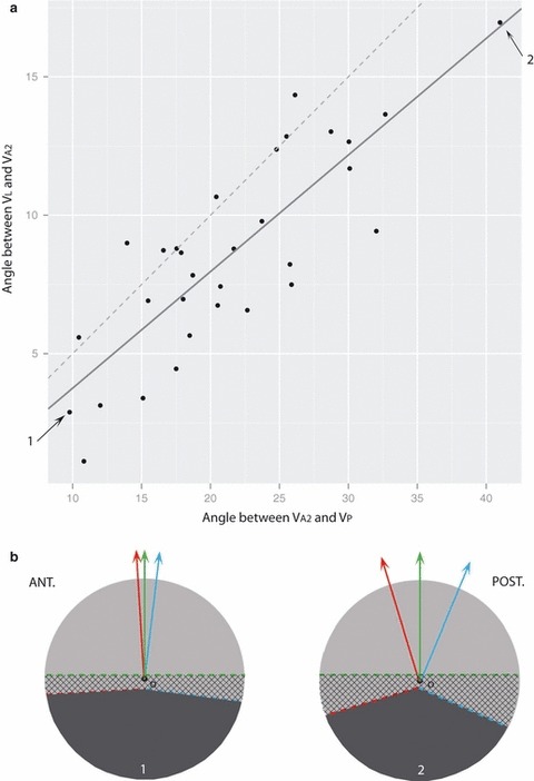
Understanding the three-dimensional orientation of the coxo-femoral joint remains a challenge as an accurate three-dimensional orientation ensure an efficient bipedal gait and posture. The quantification of the orientation of the acetabulum can be performed using the three-dimensional axis perpendicular to the plane that passes along the edge of the acetabular rim. However, the acetabular rim is not regular as an important indentation in the anterior rim was observed. An innovative cadaver study of the labrum was developed to shed light on the proper quantification of the three-dimensional orientation of the acetabulum. Dissections on 17 non-embalmed corpses were performed. Our results suggest that the acetabular rim is better represented by an anterior plane and a posterior plane rather than a single plane along the entire rim as it is currently assumed. The development of the socket from the Y-shaped cartilage was suggested to explain the different orientations in these anterior and posterior planes. The labrum forms a plane that takes an orientation in between the anterior and posterior parts of the acetabular rim, filling up inequalities of the bony rim. The vectors V(L) , V(A2) and V(P) , representing the three-dimensional orientation of the labrum, the anterior rim and the posterior rim, are situated in a unique plane that appears biomechanically dependent. The three-dimensional orientation of the acetabulum is a fundamental parameter to understand the hip joint mechanism. Important applications for hip surgery and rehabilitation, as well as for physical anthropology, were discussed.


Figures

Fig. 1
Fig. 1
Lateral view of a left acetabulum. The anterior and posterior horn tips are indicated by the letters A and D. Along the rim two inflexions can be systematically identified: B represents the most cranial inflexion where the indentation of the anterior part of the rim appears; C, the most caudal inflexion, was placed at the beginning of the curvature of the posterior horn. B and C allow the division of the rim in two parts named the anterior and posterior acetabular rims. The landmarks 1 and 2 (indicated by crosses) correspond to the insertion of the ilium and the ischium on the acetabular rim.
Fig. 2
Fig. 2
Successive points 1 mm apart were digitised along (A) the intact labrum, (B) the totality of the acetabular rim, (C) the posterior part of the acetabular rim and (D) the anterior part of the acetabular rim. With these data four planes named, respectively, PL, PT, PA and PP combined with their respective direction vector VL, VT, VA and VP were obtained. Due to a methodological problem (see text), the anterior rim was modelled using a regression plane PA2 based on points A, B and C (large points in D) resulting in a vector VA2.
Fig. 3
Fig. 3
The planes PA2 and PP, computed using the anterior and posterior acetabular rims, are not in the same plane but they formed a mean angle of 158.6 °. (a) A general view illustrating the plane PA2 of the anterior rim (in red) and the plane PP of the posterior rim (in blue). A transversal slice was observed along the dotted line and present in (b). (b) The vector VA2 (red dotted line) and VP (blue dotted line) form a mean angle of 21.4 °. The plane of the labrum is represented by the grey dotted line.
Fig. 4
Fig. 4
(a) There is a significant positive correlation between the angle VAVP and the angle VLVA (rPearson = 0.83; P < 0.0001; N = 31), which is represented in the graph by a regression line (grey solid line). The light grey dotted line represents shapes for which VL would be exactly at the middle of VA2 and VP. A comparison between the two lines shows that VL is generally closer to VA2 than VP, and that VL is near to an intermediate position between VA2 and VP when the angle VA2VP decreases. (b) Two cases were represented to illustrate the changes of the relationships between VA (in red), VP (in blue) and VL (in green) when the angle VA2VP takes its minimal or maximal value (individuals 1 and 2, respectively, marked by arrows in a). These two cases are viewed in the plane of the three vectors VL, VA2 and VP, i.e. at the perpendicular to PC. The hatched areas illustrate the height of the labrum in its anterior and posterior parts.
Fig. 5
Fig. 5
The irregularity in the morphology of the acetabular rim can be explained by the Y-shape of the growth cartilage (solid lines). The posterior part grows from the ilio-ischiatic branch, while the anterior part is formed by the ilio-pubic and ischio-pubic branches. Each branch of the Y cartilage is not submitted to the same constraints, resulting in growth in a different direction. The acetabulum is integrated in the complex biomechanical system of the hip bone. The acetabulum is surrounded by a network of different trabecular systems (thick dotted lines), which is load history dependent. A link between the orientation of the plane PC and the biomechanical loading context was identified. The points A–C, which correspond more generally to the intersection of the pubis, ilium and ischium with the acetabular rim, are located in the area of the transition between the different trabeculae, i.e. in the least constrained area. Our results showed that the plane PC is precisely aligned with the axis formed by B and C (thin dotted line) and perpendicular to the axis formed by O and A (thin dotted line), suggesting an effect of biomechanical loading on the orientation of PC. The scan of this left hip bone was performed using a Breuckmann® surface scanner and the view was chosen to display concurrently the anterior and posterior networks of the trabecular system, the sacroiliac joint from which they emerge, and to illustrate that A–C correspond to areas of transition between the different trabeculae.

Similar articles

Cited by

References

    1. Baylac M. Rmorph a morphometric library for R. 2010. Available from the author: baylac(at)mnhn.fr.
    1. Bullough P, Goodfellow J, Greenwald AS, et al. Incongruent surfaces in the human hip joint. Nature. 1968;217:1290. - PubMed
    1. Bullough P, Goodfellow J, O’Connor JJ. The relationship between degenerative changes and load-bearing in the human hip. J Bone Joint Surg Br. 1973;55:746–758. - PubMed
    1. Byers PD, Contepomi CA, Farkas TA. A post mortem study of the hip joint. Including the prevalence of the features of the right side. Ann Rheum Dis. 1970;29:15–31. - PMC - PubMed
    1. Calandruccio RA. Arthroplasty of the hip. In: Crenshaw AH, editor. Campell’s Operative Orthopaedics. Vol. 2. St Louis: CV Mosby; 1987. pp. 1213–1501.

Publication types

LinkOut - more resources