. 2011 Jul;13(3):1-18.

Three-dimensional trans-esophageal Echocardiographic Evaluation of Atrial Septal Defects: A Pictorial Essay

Affiliations

Three-dimensional trans-esophageal Echocardiographic Evaluation of Atrial Septal Defects: A Pictorial Essay

Vinay K Sharma et al. Images Paediatr Cardiol. 2011 Jul.

Abstract

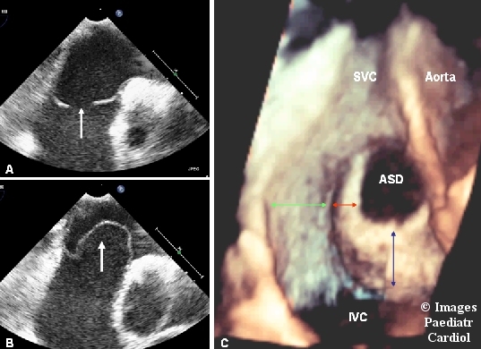
This pictorial assay illustrates the methodology of evaluating the atrial septal defects by three dimensional transesophageal echocardiography with the help of representative images. The article starts by discussing the technical details of how to acquire and crop the dataset to reconstruct the transesophageal three dimensional echocardiographic images of the inter atrial septum. Next, the anatomical details of the normal inter atrial septum are illustrated, followed by representative examples of all the possible defects of inter atrial septum. All the images have been reproduced in a uniform pattern which is similar to the view of the inter atrial septum that is seen in the real life situation by the surgeon.

Keywords: atrial septal defect; echocardiography.


Figures

Figure 1
Figure 1
Picture A, B and C are 3D TEE images of IAS from RA perspective and shows the importance of the maintaining proper gain settings during the image acquisition and the fact that it has to be individualized for every patient. Picture A is taken after optimal gain setting and shows centrally placed secundum ASD with good surrounding margins. Picture B has been taken after decreasing the gain and it can be seen that now echo dropouts have appeared near the postero-inferior margin of the defect. Picture C has been taken after increasing the gain and shows that it completely blurs the anatomical boundaries and no defect can be seen.
Figure 2
Figure 2
Picture A shows the raw 3D dataset which has been acquired in basal long axis view (bicaval view). Picture B displays the dataset after the initial cropping has removed the RA free wall and the tricuspid valve comes in view (red arrows). Picture C displays the dataset after further cropping, till aorta comes in view. Picture D displays the dataset after further cropping, till the image of IAS from right atrial perspective comes in view. Several anatomical features of IAS can be seen in great detail. The oval depression in the central part of the IAS is called fossa ovalis. It is the thinnest part of the IAS (IAS itself is very thin, being only 2 mm thick). The fossa ovalis is bounded by a thicker rim of tissue, called limbus of fossa ovalis (red arrows). It is most pronounced above and on the side of the fossa ovalis and is deficient in it's inferior part. The opening of the coronary sinus can be seen to the left of the limbus. Aorta (white arrows), SVC and IVC are also seen in this view. It is important to memorize the position of SVC, IVC, aorta and TV in relation to the IAS, because these structures are used as landmarks to define the margins of the ASD.
Figure 3
Figure 3
Picture A, B and C are 2D TEE images of a centrally situated secundum type ASD. Picture A is four chamber view and shows AV septal margin (grey arrow) and atrial margin (blue arrow). Picture B is basal short axis view and shows the retro aortic margin (green arrow). Picture C is the basal long axis (bicaval view) and shows the SVC margin (white arrow) and IVC margin (red arrow).Picture D is three dimensional en-face view of inter atrial septum from RA perspective and shows all the margins of the ASD in a single image . These margins are, clockwise from top, SVC margin (white double headed arrow) , aortic margin (green double headed arrow),IVC margin (red double headed arrow) and atrial margin (blue double headed arrow).
Figure 4
Figure 4
Picture A, B, C and D are 3D TEE view of IAS from the RA perspective. Picture A has been labeled to depict the structures being seen. Red arrow denote the position of SVC, green arrow denotes position of IVC and double headed white arrow denotes the position of aorta. The picture B is of late systole, showing the maximal diameter of ASD. Picture C is from early diastole and shows that the diameter of the ASD has started decreasing. Picture D is from late diastole when the ASD reaches its minimal diameter.
Figure 5
Figure 5
Picture A, B , C and D are 2D TEE images of an ASD with deficient aortic margin. Picture A is four chamber view from mid esophageal position and shows an intact IAS. Picture B is four chamber view taken after pulling the probe to high esophageal location and now the septal defect can be seen. This implies that the defect is superiorly situated. Picture C is basal short axis view and shows that the retro aortic margin of the defect is absent. Picture D is basal long axis (bicaval) view. The defect is still being seen but the defect size is less than that being seen in picture B, thus suggesting that the defect is anteriorly situated. So, the defect is anteriorly and superiorly situated and the aortic margins are deficient. Picture E is 3D TEE image of the ASD from RA perspective. The aortic margin (white double headed arrow) is deficient , while all other margins are quite robust (blue double headed arrow denotes the SVC margin , black double headed arrow denotes the atrial margin and red double headed arrow denotes the IVC margin).
Figure 6
Figure 6
Picture A, B, C and D are 2D TEE images of multiple ASDs. Picture A is four chamber view, showing the presence of two separate ASDs, labeled as number 1 and 2, with ASD number 2 being nearer to the aorta. Picture B is basal short axis view and confirms the presence of two separate ASDs. Picture C is bicaval view and it shows only one ASD, suggesting that one of the ASD (ASD number 2) is situated in a more anterior plane. Picture D is the 3D TEE image of IAS from RA perspective showing relative position of both the ASDs. It can be seen that both the ASDs have very stout IVC margin and are also separated by a good amount of tissues, making them suitable for closure by two separate devices. The black arrows show the Eustachian valve.
Figure 7
Figure 7
Picture A and B are 2D TEE four chamber images. Picture A shows the presence of a fossa ovalis ASD. Picture B is from same probe position and shows large aneurysm of inter atrial septum (white arrow). Picture C is a 3D TEE image of the IAS from RA perspective and very vividly demonstrates the relative position of the aneurysm and the ASD. The almost entire IVC margin (blue double headed arrow) and anterior part of the atrial margin (red double headed arrow) is aneurysmal . Remaining part of the atrial margin (green double headed arrow) is normal. This ASD was successfully closed with a septal occluder device.
Figure 8
Figure 8
Picture A and B are 2D TEE images of inter atrial septum. Picture A is four chamber view, showing the presence of an aneurysm of IAS. Picture B is basal long axis (bicaval) view, showing two separate defects (white arrows) of inter atrial septum. Careful scan of the image also shows that the second defect is situated nearer to IVC, in aneurysmal part of the IAS. Picture C is a 3D TEE image of ASD from RA perspective. The almost entire IVC margin of the larger defect is aneurysmal and the smaller ASD is situated in this aneurysmal part. The presence of the funnel around the second defect helps in differentiating the defect from an echo dropout.
Figure 9
Figure 9
Picture A, B and C are 2D TEE images of an SVC type sinus venosus defect. Picture A is four chamber view from mid esophageal position and does not show any defect. However, this view shows the flap of foramen ovale (white arrow) which rules out the possibility of presence of a fossa ovalis type defect. Picture B is four chamber view taken from a higher esophageal position and reveals the presence of a defect of atrial septum (white arrow). Picture C is basal long axis view and shows the SVC type defect (red double headed arrow) with straddling of IAS by SVC. Picture D is a 3D TEE image of the defect. A muscular rim between the defect and fossa ovalis confirms the diagnosis of sinus venosus type defect. The defect is situated very high up near the SVC orifice and the lower half of the IAS had to be excluded from the dataset (white double headed arrow) to visualize the defect.
Figure 10
Figure 10
Picture A, B and C are 2D TEE images of an IVC type sinus venosus defect. Picture A is four chamber view from mid esophageal position and does not show any defect. However, this view shows the flap of foramen ovale (white arrow) which rules out the possibility of presence of a fossa ovalis type defect. Picture B is the 4 chamber view taken from a lower esophageal position and reveals the presence of a defect of atrial septum (white arrow). Picture C is basal long axis view and shows the IVC type defect (white arrow) with straddling of the IAS by IVC. Picture D is a 3D TEE image of the defect. A muscular rim between the defect and fossa ovalis (black double headed arrow) confirms the diagnosis of IVC type defect.
Figure 11
Figure 11
Picture A is the image of the mitral valve in so called surgeon′ view (mitral valve being seen from LA perspective with aorta positioned in 11 o clock position). The red arrow denotes the fish mouth appearance of the stenotic mitral valve. Picture B shows the coexisting aortic stenosis and red arrow points to the stenotic opening of the aortic valve. Picture C is 2D TEE image in basal short axis view. The white arrow points to the aneurysm of inter atrial septum. Picture D is 3D TEE image of IAS from RA perspective. The white arrow points to the location of the aneurysm of inter atrial septum.
Figure 12
Figure 12
These pictures are from a patient who has undergone PTMC for rheumatic mitral stenosis. Picture A is 2D TEE four chamber image and shows the presence of left to right shunt across IAS. Picture B is a 3D TEE image of the ASD and shows an atrial septal defect, situated at superior border of the fossa ovalis. The shape of the post PTMC atrial septal defects is dependent on the cross sectional profile of the balloon and the angle at which the balloon penetrates the septum. In this case the defect is elongated in shape. Picture C is 3D TEE color flow image of IAS from the RA perspective and confirm the presence of the atrial septal defect. Picture D is same as picture C but taken after suppression of the color flow. The similarity of the shape in picture B confirms that it is actually the same defect as being seen in picture B.
Figure 13
Figure 13
Picture A, B and C shows measurements of an ASD by 2D TEE imaging. Picture A is 4 chamber view and the diameter measured in this view is the horizontal diameter and corresponds to the D2 measurement in the 3D image. Picture B shows diameter in basal short axis image. Picture C is the bicaval view and the diameter shown in this image is the vertical diameter and corresponds to D1 diameter in the 3D image. Picture D shows 3D TEE image of the defect and shows that all measurements can be taken in a single image.
Figure 14
Figure 14
figure A, B and C are 3D TEE images of the inter atrial septum form RA perspective, taken during the closure of a secundum ASD with a septal occluder device. Picture A shows the positioning of the catheter across the defect. Picture B shows the image of the device after it has been opened, but has not yet been released from the catheter. This image is used to evaluate the proper positioning of the device and it's relation to the surrounding margins as well as the orifices of pulmonary veins, SVC and IVC. Picture C is taken after release of the device from the catheter and confirms that the device is properly positioned. A device which is properly positioned and firmly gripping all the margins of the defect should not have excess mobility.

Similar articles

Cited by

References

    1. Dickinson DF, Arnold R, Wilkinson JL. Congenital heart disease among 160480 live born children in Liverpool 1960 to 1969- Implications for surgical treatment. Br Heart J. 1981;46:55–62. - PMC - PubMed
    1. Rome JJ, Keane JF, Perry SB, Spevak PJ, Lock JE. Double umbrella closure of atrial defects.Initial clinical applications. Circulation. 1990;82:751–8. - PubMed
    1. Das GS, Voss G, Jarvis G, Wyche K, Gunther R, Wilson RF. Experimental atrial septal defect closure with a new, transcatheter, self-centering device. Circulation. 1993;88:1754–64. - PubMed
    1. Chan KC, Godman MJ. Morphological variations of fossa ovalis atrial septal defects (secundum): feasibility for transcutaneous closure with the clam-shell device. Br Heart J. 1993;69:52–5. - PMC - PubMed
    1. Hellenbrand WE, Fahey JT, McGowan FX, Weltin GG, Kleinman CS. Transoesophageal echocardiographic guidance of transcatheter closure of atrial septal defect. Am J Cardiol. 1990;66:207–13. - PubMed

LinkOut - more resources