

A pilot trial on kinematic magnetic resonance imaging using a superconducting, horizontally opened, 1.2 T magnetic resonance system
- PMID: 22375248
- PMCID: PMC3289220
- DOI: 10.5812/asjsm.34740
A pilot trial on kinematic magnetic resonance imaging using a superconducting, horizontally opened, 1.2 T magnetic resonance system
Abstract
Purpose: This study was performed to introduce and evaluate the potential of kinematic magnetic resonance imaging (KMRI) using a high-field open-magnet magnetic resonance (MR) system.
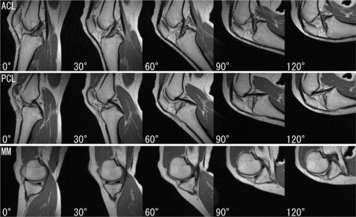
Methods: We attempted to perform KMRI of healthy volunteers' lumbar spine and knee in the lateral position and ankle in the supine position utilizing the superconducting, horizontally opened, 1.2 T MR system (OASIS, HITACHI, Tokyo, Japan). For the KMRI of the lumbar spine, the volunteer had to lie on one side while maintaining maximally anteflexed, neutral, and maximally retroflexed positions and remain still for the duration of the acquisition time for each posture. In the same way, KMRI of the knee was performed with the volunteer's knee flexed at 0°, 30°, 60°, 90°, and 120° in the lateral position, and KMRI of the ankle was performed with the volunteer's ankle in maximally dorsiflexed, neutral, and maximally plantarflexed positions while lying in the supine position.
Results: We could acquire higher quality kinematic MR images than those acquired using low-field MR systems. The spinal canal, intervertebral discs and foramina, and facet joints in lumbar spine KMRI; the ligaments, menisci and patellofemoral joint in knee KMRI; and the tibiotalar articulation and peroneal tendon in ankle KMRI were clearly depicted.
Conclusion: The results of our pilot trial indicated that a superconducting horizontally opened, 1.2 T MR system offers high-quality KMRI images and can be utilized for the kinematic diagnosis and evaluation of sports injuries.
Keywords: Joint Motion; KMRI; Kinematic; Magnetic Resonance Imaging; Open MRI.
Figures


References
-
- Shellock FG, Powers CM. Kinematic MRI of the Joints. Functional Anatomy, Kinesiology, and Clinical Applications. Boca Raton: CRC Press; 2001.
-
- Harvey SB, Smith FW, Hukins DWL. Measurement of lumbar spine flexion-extension using a low-field open-magnet magnetic resonance scanner. Invest Radiol. 1998;33:439–43. - PubMed
-
- Wildermuth S, Zanetti M, Duwell S, et al. Lumbar spine: quantitative and qualitative assessment of positional (upright flexion and extension) MR imaging and myelography. Radiology. 1998;207:391–8. - PubMed
-
- Schmid MR, Stucki G, Duewell S, et al. Changes in cross-sectional measurements of the spinal canal and intervertebral foramina as a function of body position: In vivo studies on an open-configuration MR system. Am J Roentgenol. 1999;172:1095–102. - PubMed
-
- Weishaupt D, Schmid MR, Zanetti M, et al. Positional MR imaging of the lumbar spine: Does it demonstrate nerve root compromise not visible at conventional MR imaging? Radiology. 2000;215:247–53. - PubMed
LinkOut - more resources
Full Text Sources