

Design and analysis of a novel mechanical loading machine for dynamic in vivo axial loading
- PMID: 22380131
- PMCID: PMC3298551
- DOI: 10.1063/1.3687781
Design and analysis of a novel mechanical loading machine for dynamic in vivo axial loading
Abstract
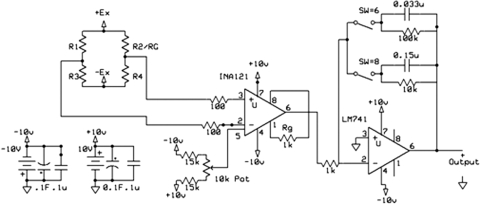
This paper describes the construction of a loading machine for performing in vivo, dynamic mechanical loading of the rodent forearm. The loading machine utilizes a unique type of electromagnetic actuator with no mechanically resistive components (servotube), allowing highly accurate loads to be created. A regression analysis of the force created by the actuator with respect to the input voltage demonstrates high linear correlation (R(2) = 1). When the linear correlation is used to create dynamic loading waveforms in the frequency (0.5-10 Hz) and load (1-50 N) range used for in vivo loading, less than 1% normalized root mean square error (NRMSE) is computed. Larger NRMSE is found at increased frequencies, with 5%-8% occurring at 40 Hz, and reasons are discussed. Amplifiers (strain gauge, linear voltage displacement transducer (LVDT), and load cell) are constructed, calibrated, and integrated, to allow well-resolved dynamic measurements to be recorded at each program cycle. Each of the amplifiers uses an active filter with cutoff frequency at the maximum in vivo loading frequencies (50 Hz) so that electronic noise generated by the servo drive and actuator are reduced. The LVDT and load cell amplifiers allow evaluation of stress-strain relationships to determine if in vivo bone damage is occurring. The strain gauge amplifier allows dynamic force to strain calibrations to occur for animals of different sex, age, and strain. Unique features are integrated into the loading system, including a weightless mode, which allows the limbs of anesthetized animals to be quickly positioned and removed. Although the device is constructed for in vivo axial bone loading, it can be used within constraints, as a general measurement instrument in a laboratory setting.
Figures


Similar articles
-
Micromechanical Loading Studies in Ex Vivo Cultured Embryonic Rat Bones Enabled by a Newly Developed Portable Loading Device.Ann Biomed Eng. 2023 Oct;51(10):2229-2236. doi: 10.1007/s10439-023-03258-2. Epub 2023 Jun 14. Ann Biomed Eng. 2023. PMID: 37314663 Free PMC article.
-
Reconstruction of bone loading conditions from in vivo strain measurements.J Biomech. 1995 Jun;28(6):739-44. doi: 10.1016/0021-9290(94)00122-k. J Biomech. 1995. PMID: 7601873
-
An extensometer for global measurement of bone strain suitable for use in vivo in humans.J Biomech. 2001 Mar;34(3):385-91. doi: 10.1016/s0021-9290(00)00197-4. J Biomech. 2001. PMID: 11182131
-
Multiscale computational and experimental approaches to elucidate bone and ligament mechanobiology using the ulna-radius-interosseous membrane construct as a model system.Technol Health Care. 2012;20(5):363-78. doi: 10.3233/THC-2012-0686. Technol Health Care. 2012. PMID: 23079942 Review.
-
Biomechanical and biophysical environment of bone from the macroscopic to the pericellular and molecular level.J Mech Behav Biomed Mater. 2015 Oct;50:104-22. doi: 10.1016/j.jmbbm.2015.04.021. Epub 2015 Apr 24. J Mech Behav Biomed Mater. 2015. PMID: 26119589 Review.
Cited by
-
Magnitude of loads influences the site of failure of highly curved bones.J Mech Behav Biomed Mater. 2014 Feb;30:274-8. doi: 10.1016/j.jmbbm.2013.11.018. Epub 2013 Dec 2. J Mech Behav Biomed Mater. 2014. PMID: 24361931 Free PMC article.
-
Collagen Fibrils in Skin Orient in the Direction of Applied Uniaxial Load in Proportion to Stress while Exhibiting Differential Strains around Hair Follicles.Materials (Basel). 2015 Apr 20;8(4):1841-1857. doi: 10.3390/ma8041841. Materials (Basel). 2015. PMID: 28788035 Free PMC article.
References
Publication types
MeSH terms
Grants and funding
LinkOut - more resources
Full Text Sources