. 2012;7(2):e31770.
doi: 10.1371/journal.pone.0031770. Epub 2012 Feb 22.

Catching a ball at the right time and place: individual factors matter

Affiliations

Catching a ball at the right time and place: individual factors matter

Benedetta Cesqui et al. PLoS One. 2012.

Abstract

Intercepting a moving object requires accurate spatio-temporal control. Several studies have investigated how the CNS copes with such a challenging task, focusing on the nature of the information used to extract target motion parameters and on the identification of general control strategies. In the present study we provide evidence that the right time and place of the collision is not univocally specified by the CNS for a given target motion; instead, different but equally successful solutions can be adopted by different subjects when task constraints are loose. We characterized arm kinematics of fourteen subjects and performed a detailed analysis on a subset of six subjects who showed comparable success rates when asked to catch a flying ball in three dimensional space. Balls were projected by an actuated launching apparatus in order to obtain different arrival flight time and height conditions. Inter-individual variability was observed in several kinematic parameters, such as wrist trajectory, wrist velocity profile, timing and spatial distribution of the impact point, upper limb posture, trunk motion, and submovement decomposition. Individual idiosyncratic behaviors were consistent across different ball flight time conditions and across two experimental sessions carried out at one year distance. These results highlight the importance of a systematic characterization of individual factors in the study of interceptive tasks.


Conflict of interest statement

Competing Interests: The authors have declared that no competing interests exist.

Figures

Figure 1
Figure 1. Experimental apparatus and trial selection.
(A) Subjects were standing at a distance of 6 m in front of a screen with a hole through which balls were projected by a launching apparatus positioned behind the screen. (B) Ball arrival position distribution on the frontal plane for the all selected subjects and trial selection according to a normalized arrival height criterion. Scatter plots of the y-z coordinates (frontal plane) normalized with respect to shoulder height and arm length of all caught balls at the x coordinate of the shoulder at launch time. Trials selected for the analysis (black dots) are only those inside the z coordinate ranges delimited by the dashed lines. Gray dots represent trials with a normalized arrival ball height outside the height ranges.
Figure 2
Figure 2. Example of wrist kinematic differences across selected subjects.
Wrist trajectory (first row), x-z tangential velocity profiles (second row), and velocity components in the sagittal plane (third row) are shown for individual trials of each subject (columns 1–6) in the T2Z1 condition as well as averaged across trials for each subject (column 7). Black lines are relative to the trials recorded in a first experimental session. Red lines are relative to trials in the same experimental condition recorded during a second session carried out one year later. All trajectories are plotted up to 100 ms after the impact event, and translated to align the shoulder position at launch time (indicated by the black square).
Figure 3
Figure 3. Inter-individual differences in wrist velocity at maximum speed, minimum speed, and impact.
Wrist velocity components (mean ± SE; SE are reported only when number of trials per block was larger than 2) in the sagittal plane (x, anterior-posterior axis; z vertical axis) for each one of the three flight time conditions (T, indicated by different marker shapes) are illustrated separately for the two different arrival heights (first row: high, second row: low). Subject color coding is the same as in Figure 2.
Figure 4
Figure 4. Interception point along the ball trajectory.
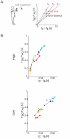
(A) Left panel: schematic representation of the interception point index (computed as the ratio between the BC and AB ball trajectory arc lengths, see Methods). Right panel: for each flight time condition (T1–T3), subjects impact point along ball trajectory (normalized with respect to subject arm length) was uniquely determined by the movement time, hence the value of the difference between the extrapolated time of arrival of the ball at the frontal plane (tC) and the impact time (tB). However, for different flight times, subjects are free to vary tB and impact the ball at the same normalized distance (vertical line labeled “const distance”) or to catch the ball closer to their shoulder (horizontal line labeled “const time”). (B) Scatter plots of the interception index vs. tC−tB (mean ± SE across trials in the same conditions; SE are reported only when number of trials per block was larger than 2). A value of I = 0 indicates a catch at C while I = 1 indicates a catch in correspondence of the first possible interception point (A point), computed as the interception between the ball trajectory and the sphere centered at the shoulder joint of radius equal to arm length. It was not possible to determine S3 behavior in the T3Z2 condition because the shoulder marker detached and was missing throughout the entire block. Subject color coding as in Figures 2 and 3.
Figure 5
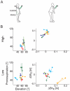
Figure 5. Wrist posture and trunk displacement at impact.
(A) Examples of different body and arm postures at impact in two subjects (S5 left, S6 right). (B) Left panel: scatter plots of the forearm pronosupination angle vs. forearm elevation angle (mean ± SE across trials of the same condition; SE are reported only when number of trials per block was larger than 2). Right panel: shoulder displacement in the sagittal (x-z) plane between launch and impact times. It was not possible to determine Subject 3 behavior in the T3Z2 condition since the shoulder marker detached and was missing throughout the entire block. Subject color coding as in Figures 2 and 3.
Figure 6
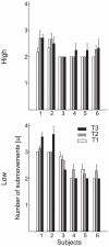
Figure 6. Frequency of the submovement components.
Mean and SD across trials of the number of submovement components extracted by the algorithm for the two ball arrival heights (different rows) and three flight times (different shading) for each subject. Different subjects showed different submovement structures characterized by different mean numbers of submovements.
Figure 7
Figure 7. Classification of movements according to submovement composition.
(A) Examples of the 3 types of submovement decomposition characterizing all observed wrist velocity profiles. (B) Submovement duration distribution in the T2Z1 experimental condition, for 3 of the 6 selected participants, representative of the first three movement types. Each submovement is reported in a different line. The colored bars represent the mean duration and the horizontal lines the SD of the onset and of the offset of each submovement. Subjects presented a robust behavior across trials of the same block, as shown by stable segments duration distribution. (C) Frequency distribution of submovement types (expressed in percentage) for each ball arrival height and for each subject; different hand speed profile decomposition structures were sometimes observed when catching lower or higher targets, as in the case of subjects 2 and 3.
Figure 8
Figure 8. Example of wrist kinematic features of excluded subjects.
Left panel: wrist trajectory averaged across all caught and intercepted trials in the T2Z1 condition are shown for all 14 subjects enrolled in the study; all trajectories are plotted up to 100 ms after the impact event, and translated to align the shoulder position at launch time (indicated by the black square). Right panel: velocity components in the sagittal plane in the T2Z1 condition. Black lines and square markers are relative to the excluded subject group.

Similar articles

Cited by

References

    1. Lacquaniti F, Soechting JF, Terzuolo SA. Path constraints on point-to-point arm movements in three-dimensional space. Neuroscience. 1986;17:313–324. - PubMed
    1. Flash T, Hogan N. The coordination of arm movements: an experimentally confirmed mathematical model. J Neurosci. 1985;5:1688–1703. - PMC - PubMed
    1. Atkeson CG, Hollerbach JM. Kinematic features of unrestrained vertical arm movements. J Neurosci. 1985;5:2318–2330. - PMC - PubMed
    1. Morasso P. Spatial control of arm movements. Exp Brain Res. 1981;42:223–227. - PubMed
    1. Berret B, Chiovetto E, Nori F, Pozzo T. The manifold reaching paradigm: how do we handle target redundancy? J Neurophysiol 2011 - PubMed

Publication types