

Computational modeling of axonal microtubule bundles under tension
- PMID: 22385845
- PMCID: PMC3283805
- DOI: 10.1016/j.bpj.2011.11.4024
Computational modeling of axonal microtubule bundles under tension
Abstract
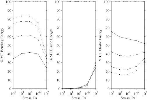
Microtubule bundles cross-linked by tau protein serve a variety of neurological functions including maintaining mechanical integrity of the axon, promoting axonal growth, and facilitating cargo transport. It has been observed that axonal damage in traumatic brain injury leads to bundle disorientation, loss of axonal viability, and cognitive impairment. This study investigates the initial mechanical response of axonal microtubule bundles under uniaxial tension using a discrete bead-spring representation. Mechanisms of failure due to traumatic stretch loading and their impact on the mechanical response and stability are also characterized. This study indicates that cross-linked axonal microtubule bundles in tension display stiffening behavior similar to a power-law relationship from nonaffine network deformations. Stretching of cross-links and microtubule bending were the primary deformation modes at low stresses. Microtubule stretch was negligible up to tensile stresses of ∼1 MPa. Bundle failure occurred by failure of cross-links leading to pull-out of microtubules and loss of bundle integrity. This may explain the elongation, undulation, and delayed elasticity of axons following traumatic stretch loading. More extensively cross-linked bundles withstood higher tensile stresses before failing. The bundle mechanical behavior uncovered by these computational techniques should guide future experiments on stretch-injured axons.
Copyright © 2012 Biophysical Society. Published by Elsevier Inc. All rights reserved.
Figures


Similar articles
-
Torsional behavior of axonal microtubule bundles.Biophys J. 2015 Jul 21;109(2):231-9. doi: 10.1016/j.bpj.2015.06.029. Biophys J. 2015. PMID: 26200859 Free PMC article.
-
A viscoelastic model for axonal microtubule rupture.J Biomech. 2015 May 1;48(7):1241-7. doi: 10.1016/j.jbiomech.2015.03.007. Epub 2015 Mar 20. J Biomech. 2015. PMID: 25835789
-
Mechanical Effects of Dynamic Binding between Tau Proteins on Microtubules during Axonal Injury.Biophys J. 2015 Dec 1;109(11):2328-37. doi: 10.1016/j.bpj.2015.09.010. Biophys J. 2015. PMID: 26636944 Free PMC article.
-
Microtubules as a signal hub for axon growth in response to mechanical force.Biol Chem. 2023 Sep 8;405(1):67-77. doi: 10.1515/hsz-2023-0173. Print 2024 Jan 29. Biol Chem. 2023. PMID: 37674311 Review.
-
The role of mechanics in axonal stability and development.Semin Cell Dev Biol. 2023 May 15;140:22-34. doi: 10.1016/j.semcdb.2022.06.006. Epub 2022 Jun 30. Semin Cell Dev Biol. 2023. PMID: 35786351 Free PMC article. Review.
Cited by
-
Viscoelastic Response of Neurofilaments: An Atomistic Simulation Approach.Biomolecules. 2021 Apr 7;11(4):540. doi: 10.3390/biom11040540. Biomolecules. 2021. PMID: 33917073 Free PMC article.
-
Buckling behavior of individual and bundled microtubules.Biophys J. 2015 Apr 7;108(7):1718-1726. doi: 10.1016/j.bpj.2015.01.030. Biophys J. 2015. PMID: 25863063 Free PMC article.
-
Simulating tubulin-associated unit transport in an axon: using bootstrapping for estimating confidence intervals of best-fit parameter values obtained from indirect experimental data.Proc Math Phys Eng Sci. 2017 May;473(2201):20170045. doi: 10.1098/rspa.2017.0045. Epub 2017 May 3. Proc Math Phys Eng Sci. 2017. PMID: 28588409 Free PMC article.
-
Coarse-Grained Simulation of Mechanical Properties of Single Microtubules With Micrometer Length.Front Mol Biosci. 2021 Feb 15;7:632122. doi: 10.3389/fmolb.2020.632122. eCollection 2020. Front Mol Biosci. 2021. PMID: 33659274 Free PMC article.
-
Utilizing a Structural Mechanics Approach to Assess the Primary Effects of Injury Loads Onto the Axon and Its Components.Front Neurol. 2018 Aug 6;9:643. doi: 10.3389/fneur.2018.00643. eCollection 2018. Front Neurol. 2018. PMID: 30127763 Free PMC article.
References
-
- Goldstein L.S.B., Yang Z.H. Microtubule-based transport systems in neurons: the roles of kinesins and dyneins. Annu. Rev. Neurosci. 2000;23:39–71. - PubMed
-
- Guzik B.W., Goldstein L.S. Microtubule-dependent transport in neurons: steps towards an understanding of regulation, function and dysfunction. Curr. Opin. Cell Biol. 2004;16:443–450. - PubMed
-
- Fadić R., Vergara J., Alvarez J. Microtubules and caliber of central and peripheral processes of sensory axons. J. Comp. Neurol. 1985;236:258–264. - PubMed
-
- Conde C., Cáceres A. Microtubule assembly, organization and dynamics in axons and dendrites. Nat. Rev. Neurosci. 2009;10:319–332. - PubMed
MeSH terms
Substances
LinkOut - more resources
Full Text Sources
Molecular Biology Databases
