. 2012 Jun;107(12):3543-58.
doi: 10.1152/jn.01101.2011. Epub 2012 Mar 7.

Fabrication of an inexpensive, implantable cooling device for reversible brain deactivation in animals ranging from rodents to primates

Affiliations

Fabrication of an inexpensive, implantable cooling device for reversible brain deactivation in animals ranging from rodents to primates

Dylan F Cooke et al. J Neurophysiol. 2012 Jun.

Abstract

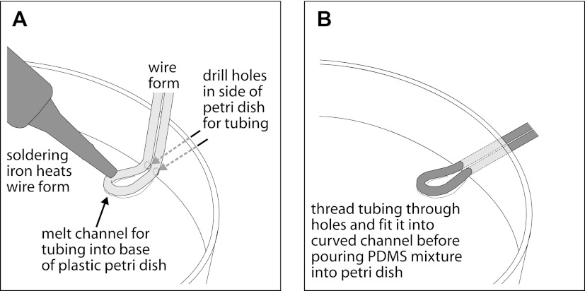
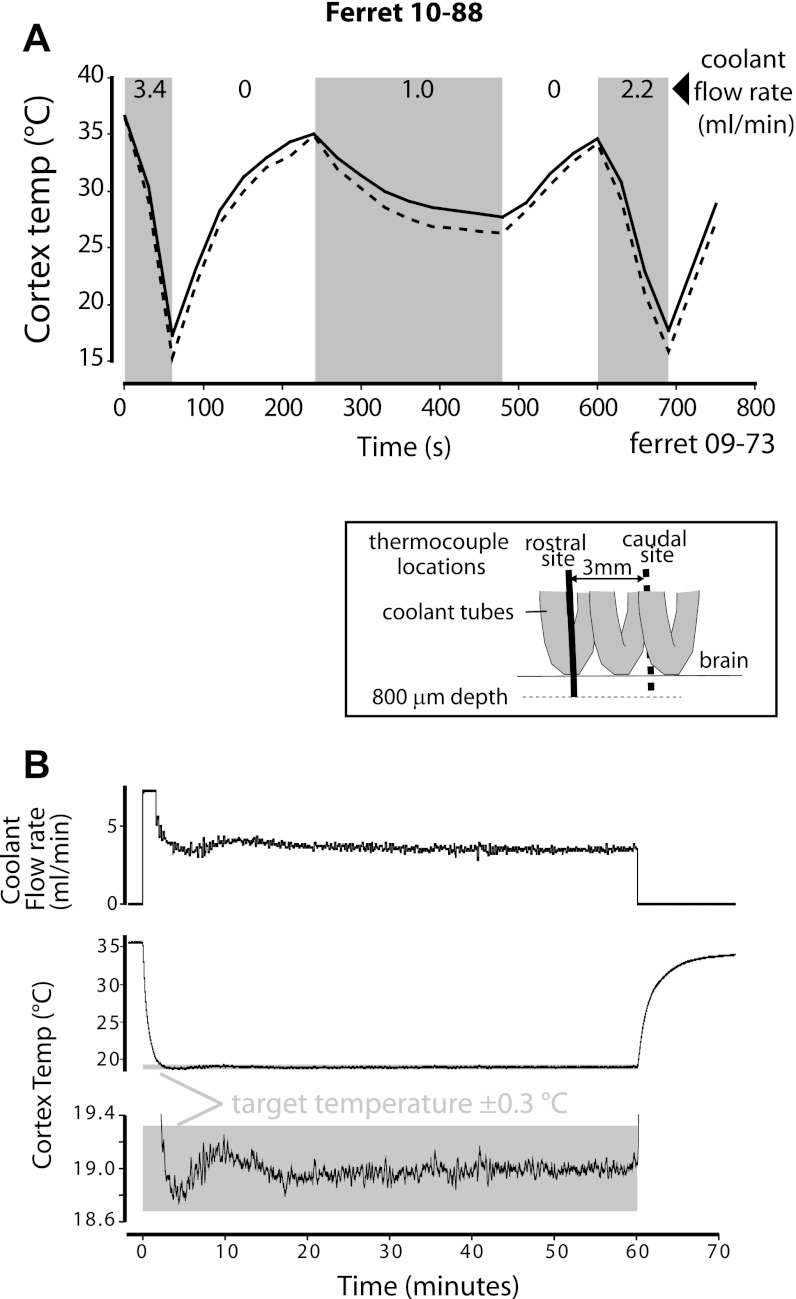
We have developed a compact and lightweight microfluidic cooling device to reversibly deactivate one or more areas of the neocortex to examine its functional macrocircuitry as well as behavioral and cortical plasticity. The device, which we term the "cooling chip," consists of thin silicone tubing (through which chilled ethanol is circulated) embedded in mechanically compliant polydimethylsiloxane (PDMS). PDMS is tailored to compact device dimensions (as small as 21 mm(3)) that precisely accommodate the geometry of the targeted cortical area. The biocompatible design makes it suitable for both acute preparations and chronic implantation for long-term behavioral studies. The cooling chip accommodates an in-cortex microthermocouple measuring local cortical temperature. A microelectrode may be used to record simultaneous neural responses at the same location. Cortex temperature is controlled by computer regulation of the coolant flow, which can achieve a localized cortical temperature drop from 37 to 20°C in less than 3 min and maintain target temperature to within ±0.3°C indefinitely. Here we describe cooling chip fabrication and performance in mediating cessation of neural signaling in acute preparations of rodents, ferrets, and primates.


Figures

Fig. 1.
Fig. 1.
Schematic illustration of equipment used during cooling. A: a peristaltic pump pushes ethanol through silicon tubing (thick gray line) that runs though a dry ice bath and then the cooling chip positioned on the cortex. A microthermocouple sends brain temperature data to a computer-hardware interface, a Power1401 mk II. An algorithm specified in Spike2 software uses this brain temperature as feedback to regulate pump speed, which is controlled by a voltage sent from the Power1401 to the pump. Neural activity from the electrode in the brain under the cooling device is amplified and recorded. B: connections between thermocouple reader and microthermocouple measuring brain temperature. C: tubing and tubing junctions. PDMS, polydimethylsiloxane.
Fig. 2.
Fig. 2.
Heat exchange devices (“cooling chips”) for gyral and sulcal cooling. A coil-design gyral cooling chip is shown in a side (A) and bottom view (B). A drawing of the side (C) and bottom (D) of the device shows components labeled. The device consists of silicon tubing embedded in PDMS that can be trimmed to size during surgery. Preformed ports provide access to cortex below the cooling chip for microthermocouples and/or electrodes. A typical small coil design chip weighs about 0.4 g. Sulcal loop designs are shown from a side (E) and front view (G), and drawings of these sulcal chips are shown in F and H. The PDMS serves to insulate the opposite bank of the sulcus from cooling. The sulcal loop design (E–H) is smaller (0.16 g) than the coil design. For all of these cooling devices, microthermocouples and/or electrodes are positioned after the cooling chip is in place.
Fig. 3.
Fig. 3.
Instructions for fabrication of cooling devices for implantation on gyral surface. A: create a temporary framework by cutting holes in an acetate sheet (top) through which silicone tubing is threaded to form a coil or helix with both ends exiting opposite to the side that will contact the cortex. Insert metal rods (bottom) through the acetate to form a template for holes within the coiled region for insertion of electrodes and thermocouples. B: position acetate at an angle with the cortex side up and drip only enough uncured PDMS to close remaining gaps in acetate around the tubing and rods. C: after the PDMS has cured, position the cooling chip with the side that will contact the cortex facing up (inset) on oven rack, add second PDMS layer, and cure. D: position the chip with cortex side down and secure tube ends above to create desired tube exit angle (inset). Add third PDMS layer. E: before third PDMS layer is fully cured, slide fluorinated ethylene propylene (FEP) sleeves (dark gray) down tubing and press into PDMS. F: add fourth PDMS layer to protect and insulate top of coils. After curing, remove rods, providing paths for microthermocouples, guide tubes, and/or electrodes.
Fig. 4.
Fig. 4.
Instructions for fabrication of cooling devices for implantation in sulcus. Shape a wire (same diameter as tubing) with pliers, and then place it on the bottom of a plastic petri dish and heat to melt a channel (A). Drill holes of the same diameter in base of petri dish side. Thread tubing through holes and fit into channel in bottom of dish (B). Not shown: pour liquid PDMS mixture into dish to desired depth and allow to cure; break dish to extract cooling device; and trim excess PDMS.
Fig. 5.
Fig. 5.
Surgical procedures for acute use of the gyral cooling device are illustrated (A–C). See text for details.
Fig. 6.
Fig. 6.
Parameters affecting cortical cooling. A: cortical temperature was measured at different constant pump speeds in ferret 09-73. Measurements were made simultaneously at caudal (dashed lines) and rostral (solid lines) locations under a gyral design cooling chip (see inset, A). The similarities of the dashed and solid traces (corresponding to the caudal and rostral recording sites) indicate that the cooling properties across the chip were fairly uniform. Faster coolant flow rates generated faster cortical cooling. Shaded areas indicate time periods when the pump is on; numbers at top indicate the pump speed in ml/min. B: use of feedback to maintain a stable cortical temperature. Unlike in A, where the pump was fixed at various constant speeds, here an algorithm controlling coolant pump speed (top plot, flow rate) with feedback from cortex temperature regulated the cooling of cortex to 19°C and maintained that temperature to within 0.3°C for 60 min (ferret 10-88). Bottom plots show temperature data at 2 different y-scales. Gray boxes indicate experimenter-specified target temperatures (±0.3°C). All cooling chips used to generate data for this figure were the gyral design constructed from tubing with 0.51-mm ID.
Fig. 7.
Fig. 7.
Automated feedback control of brain temperature (bottom trace) by regulation of coolant flow rate (top trace) in anesthetized monkey 10-159. Temperature was recorded from a microthermocouple in cortex 600 μm below a cooling chip located on the pial surface of area 2. Gray boxes indicate experimenter-specified target temperatures (±0.3°C). Target temperature was achieved in <60 s. Overshoot was <0.5°C, and postovershoot was well within ±0.3°C. Resting temperature (∼35°C) was several degrees lower than normal because brain was exposed to the air. Automated feedback control performance was similar in awake monkeys.
Fig. 8.
Fig. 8.
Differential cooling of sulcal banks. Temperature was measured in both banks of the intraparietal sulcus in monkey 10-172 while a sulcal cooling chip was activated. In the schematic diagram at right, the thermocouple on the bank exposed directly to the coolant tubing (non-insulated) is shown as a solid line. The thermocouple on the bank insulated by a layer of PDMS is shown as a dashed line. Top trace shows coolant flow rate. Middle traces show temperature in the non-insulated (solid line) and insulated (dashed line) banks of cortex. Bottom trace is the difference (Δ) in temperature between the banks.
Fig. 9.
Fig. 9.
Spatial extent of cooling in monkey 10-159. Microthermocouples were lowered into the brain both through a port in the cooling chip (dashed white line between coolant tubes) and at 3 locations lateral to the chip. For a target temperature of 22.5°C at a depth of 1,000 μm under the cooling chip, temperature was also measured at various depths and lateral distances from the cooling device. Each location is color-coded by temperature (see key, top right). Under these conditions, cortex lateral to the chip was substantially warmer than cortex directly under the chip.
Fig. 10.
Fig. 10.
Spontaneous and sensory-driven neural activity in area 3b of ferret 09-31 during cooling. The receptive field for neurons below the chip (in cortical layer 4) was determined and systematically stimulated while the cortex was locally cooled, and neural activity and local cortical temperature were monitored simultaneously. A: temperature (gray trace) and cortical activity (black trace) during 2 consecutive cooling sessions. Coolant flow rate was controlled manually. Bottom panels in A show expanded views of neural activity at different time periods over the 2 cooling sessions. Tick marks below these traces indicate the timing of tactile stimulation. The receptive field on the face of the ferret was manually stimulated with the use of a paintbrush at ∼2 Hz. B: spike rasters aligned to approximate onset of manual stimulation (left). Each row of rasters is 1 presentation trial consisting of light cutaneous stimulation above the naris. Neural responses declined when temperature declined. (Note that in this pilot study, stimulus timing for each trial was imperfectly recorded by a coincident keyboard input; thus stimulus-response alignment is approximate.) At right, temperature data (gray trace) are shown with mean neural activity (black traces), temporally aligned to rasters. Solid black trace is driven activity during stimulation, and dotted black trace is spontaneous activity between stimuli; both are moving averages across trials during 10 s. Solid and dotted black lines below rasters at left mark the sampling windows for corresponding traces at right.
Fig. 11.
Fig. 11.
Spontaneous and sensory-driven neural activity in area 1 of monkey 10-21 during cooling. Details are similar to Fig. 10, except for the following. The receptive field on the hand of the monkey was stimulated by a stream of compressed air regulated by Spike2 software. Stimulus timing is therefore much more precisely known than for the study depicted in Fig. 10. The 1-Hz air puff had a duration of 300 ms and a pressure of ∼20 lb/in2.
Fig. 12.
Fig. 12.
Cooling of cortex following chronic implantation of cooling chip. A: 52 days postimplantation in monkey 10-172. Top trace is coolant pump speed. Dashed temperature trace is from microthermocouple in area 7b, 6 mm away from the active cooling chip. B: 15 days postimplantation in ferret 09-41. Gray box indicates cooling period. C: 4 days postimplantation in rat 08-116.
Fig. 13.
Fig. 13.
Magnetic-resonance (MR) compatibility. MR compatibility was tested using a 3T Siemens (Erlangen, Germany) Trio scanner at the University of California, Davis Imaging Research Center. T1-weighted high-resolution anatomic images were acquired using an MP-RAGE (magnetization-prepared rapid-acquisition gradient-echo) sequence (repetition time, 2,500 ms; echo time, 4.32 ms; flip angle, 12°; matrix size, 256 × 256). A coil-design cooling device was secured to the surface of an orange. The fine metal thermocouple was positioned within the device, several millimeters into the orange. The coolant tubing was filled with gadolinium solution to aid visualization. The device plus thermocouple caused little or no distortion in the structural scans.

Similar articles

Cited by

References

    1. Alexander GE, Fuster JM. Effects of cooling prefrontal cortex on cell firing in the nucleus medialis dorsalis. Brain Res 61: 93–105, 1973 - PubMed
    1. Alvarado JC, Stanford TR, Vaughan JW, Stein BE. Cortex mediates multisensory but not unisensory integration in superior colliculus. J Neurosci 27: 12775–12786, 2007 - PMC - PubMed
    1. Antunes FM, Malmierca MS. Effect of auditory cortex deactivation on stimulus-specific adaptation in the medial geniculate body. J Neurosci 31: 17306–17316, 2011 - PMC - PubMed
    1. Aronov D, Fee MS. Analyzing the dynamics of brain circuits with temperature: design and implementation of a miniature thermoelectric device. J Neurosci Methods 197: 32–47, 2011 - PMC - PubMed
    1. Benita M, Conde H. Effects of local cooling upon conduction and synaptic transmission. Brain Res 36: 133–151, 1972 - PubMed

Publication types

MeSH terms