Comparative Study
. 2012 Apr 18;53(4):1852-60.
doi: 10.1167/iovs.11-9309.

Influence of clinically invisible, but optical coherence tomography detected, optic disc margin anatomy on neuroretinal rim evaluation

Affiliations
Comparative Study

Influence of clinically invisible, but optical coherence tomography detected, optic disc margin anatomy on neuroretinal rim evaluation

Alexandre S C Reis et al. Invest Ophthalmol Vis Sci. .

Abstract

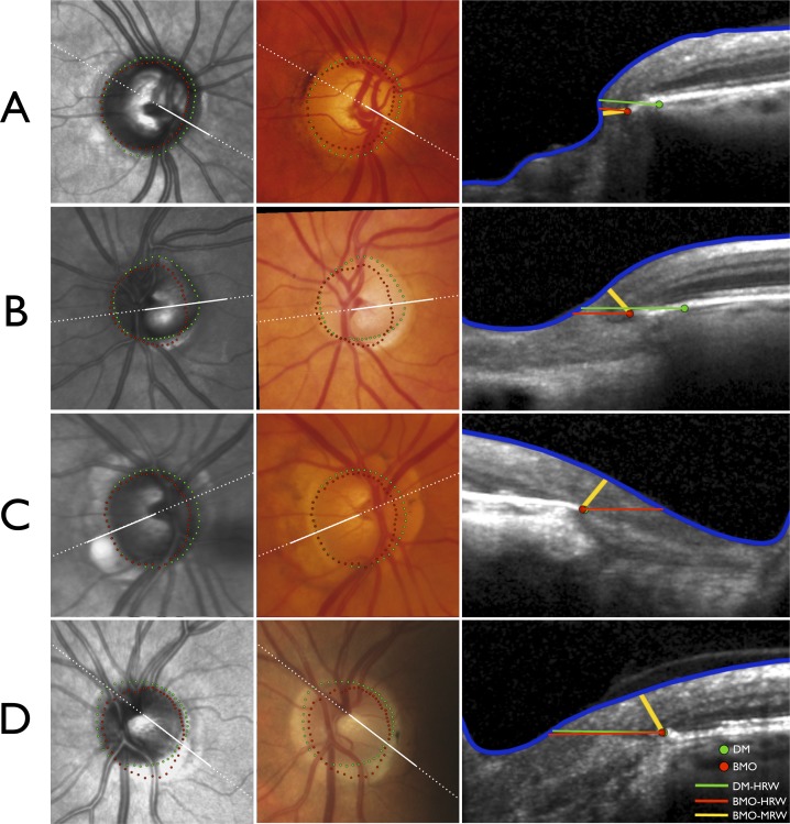
Purpose: We previously demonstrated that most eyes have regionally variable extensions of Bruch's membrane (BM) inside the clinically identified disc margin (DM) that are clinically and photographically invisible. We studied the impact of these findings on DM- and BM opening (BMO)-derived neuroretinal rim parameters.

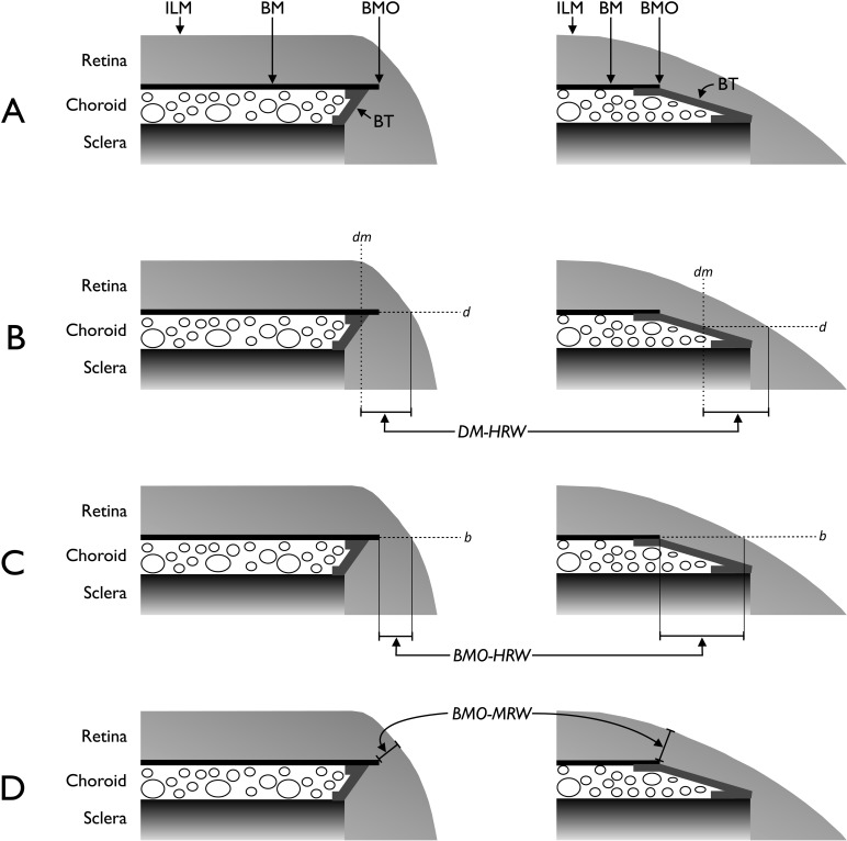
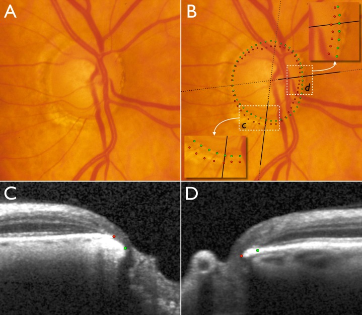
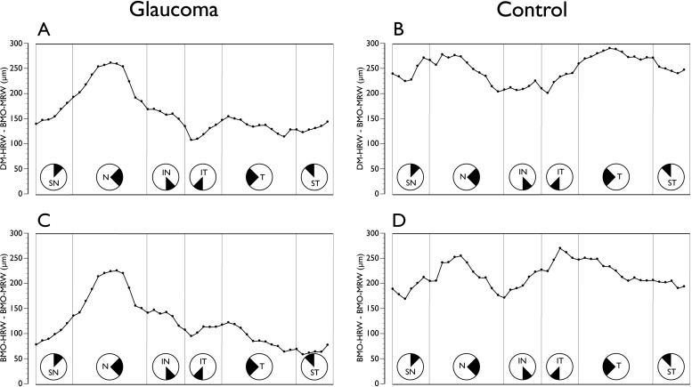
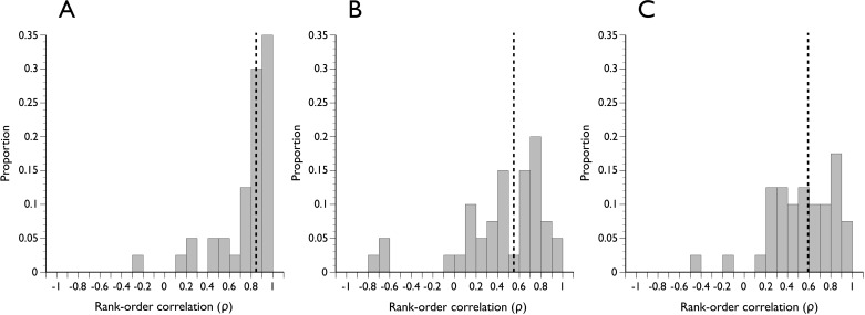
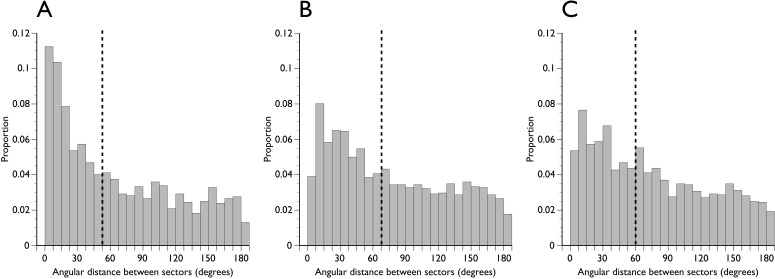
Methods: Disc stereo-photography and spectral domain optical coherence tomography (SD-OCT, 24 radial B-scans centered on the optic nerve head) were performed on 30 glaucoma patients and 10 age-matched controls. Photographs were colocalized to SD-OCT data such that the DM and BMO could be visualized in each B-scan. Three parameters were computed: (1) DM-horizontal rim width (HRW), the distance between the DM and internal limiting membrane (ILM) along the DM reference plane; (2) BMO-HRW, the distance between BMO and ILM along the BMO reference plane; and (3) BMO-minimum rim width (MRW), the minimum distance between BMO and ILM. Rank-order correlations of sectors ranked by rim width and spatial concordance measured as angular distances between equivalently ranked sectors were derived.

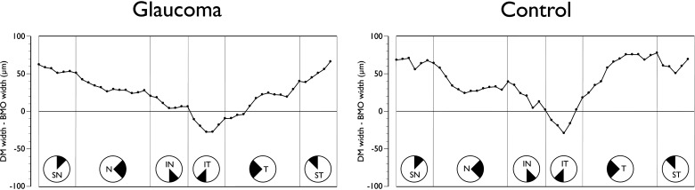
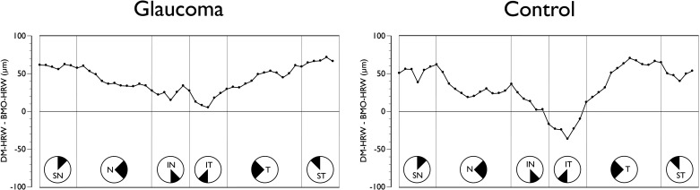
Results: The average DM position was external to BMO in all quadrants, except inferotemporally. There were significant sectoral differences among all three rim parameters. DM-HRW and BMO-HRW sector ranks were better correlated (median ρ = 0.84) than DM-HRW and BMO-MRW (median ρ = 0.55), or BMO-HRW and BMO-MRW (median ρ = 0.60) ranks. Sectors with the narrowest BMO-MRW were infrequently the same as those with the narrowest DM-HRW or BMO-HRW.

Conclusions: BMO-MRW quantifies the neuroretinal rim from a true anatomical outer border and accounts for its variable trajectory at the point of measurement.


Figures

Figure 1.
Figure 1.
Schematic representations of the neuroretinal rim parameters. (A) Salient anatomical features of the optic disc margin in internally oblique border tissue (BT) configuration (left) where BT extends internally from the anterior scleral opening to fuse with BM and externally oblique BT configuration (right) where BT extends externally from the anterior scleral opening to fuse with BM. For simplicity, the retinal pigment epithelium is not shown. (B) Representation of DM-HRW, the distance from the projection (dm) of the DM from the optic disc photograph to the ILM in the DM reference plane (d). (C) Representation of BMO-HRW, the distance from BMO to the ILM in the BMO reference plane (b). (D) Representation of BMO-MRW, the minimum distance from BMO to the ILM irrespective of the plane. Horizontal rim width measurements (B and C) depend on the trajectory of the retinal nerve fiber layer at the point of measurement resulting in larger measurements when the trajectory is more horizontal (right compared with left).
Figure 2.
Figure 2.
Disc photograph and two (of 24) SD-OCT radial B-scans of the right optic nerve head of a glaucoma patient. (A) Disc photograph with localized cupping and apparently very little or no neuroretinal rim remaining in the inferotemporal sector. (B) Clinical DM positions obtained from examination of stereo disc photographs (green) and projected BMO (red) positions obtained from SD-OCT scans. Insets show magnified areas in c and d. Dotted black lines indicate the orientation of the radial B-scans and bold solid black lines indicate the section of the B-scans shown in C and D. (C) B-scan corresponding to inset c. (D) B-scan corresponding to inset in d. In the inferotemporal section (c and C), BMO is external to DM. In this quadrant, SD-OCT detects rim tissue that is not clinically evident in the photograph. In the nasal section (d and D), BMO is internal to DM and SD-OCT detects a narrower rim than clinically apparent.
Figure 3.
Figure 3.
Sectoral mean difference plot of clinical DM width and BMO width from the BMO center in glaucoma patients (left) and age-matched controls (right). All data are converted to right-eye format and data points represent the 48 sector positions obtained from the 24 radial B-scans. SN, superior nasal; N, nasal; IN, inferonasal; IT, inferotemporal; T, temporal; ST, superotemporal.
Figure 4.
Figure 4.
Sectoral mean difference plot of clinical DM-HRW and BMO-HRW in glaucoma patients (left) and age-matched controls (right). All data are converted to right-eye format and data points represent the 48 sector positions obtained from the 24 radial B-scans. SN, superior nasal; N, nasal; IN, inferonasal; IT, inferotemporal; T, temporal; ST, superotemporal.
Figure 5.
Figure 5.
Comparison of conventional horizontal rim width measurements to BM-MRW. (A) Sectoral mean difference plot of clinical DM-HRW and BMO-MRW in glaucoma patients and (B) in age-matched controls. (C) Sectoral mean difference plot of BMO-HRW and BMO-MRW in glaucoma patients and (D) in age-matched controls. All data are converted to right-eye format and data points represent the 48 sector positions obtained from the 24 radial B-scans. SN, superior nasal; N, nasal; IN, inferonasal; IT, inferotemporal; T, temporal; ST, superotemporal.
Figure 6.
Figure 6.
Four illustrative cases (A–D) demonstrating the impact of variations in optic nerve head (ONH) anatomy on neuroretinal rim measurements. Infrared image from anatomical SD-OCT (left), registered optic disc photograph (center) and SD-OCT B-scans (right). Dashed white lines indicate the orientation of the radial B-scans and solid white lines indicate the section of the B-scans shown. (A) Right ONH of a glaucoma patient with extension of BMO internal to the clinically visible DM in all sectors except temporally resulting in DM-HRW being erroneously larger than BMO-HRW or BMO-MRW. (B) Significant mismatch between DM and BMO in the left ONH of a glaucoma patient. In the radial section shown in the temporal sector, DM-HRW is erroneously larger than BMO-HRW; however, because the trajectory of the nerve fiber layer is more parallel to the DM and BMO plane, BMO-MRW is considerably smaller. (C) Right ONH of a glaucoma patient with internal extension of BM in the nasal half and the superior temporal sector of the disc. Although the DM and BMO almost coincide in the radial section shown in the temporal sector yielding similar DM-HRW and BMO-HRW measurements, BMO-MRW is substantially smaller. (D) Left ONH of a healthy subject with significant mismatch between DM and BMO, with DM internal to BMO in the inferior temporal quadrant and BMO internal to DM in the remainder of the disc. Although the DM and BMO almost coincide in the radial section shown with similar DM-HRW and BMO-HRW measurements, BMO-MRW is substantially smaller owing to the trajectory of the nerve fiber layer.
Figure 7.
Figure 7.
Distribution of Spearman rank-order correlation coefficients in all subjects of ranks of optic nerve head sector positions according to the width of the neuroretinal rim. The magnitude of correlation indicates the degree to which sectors are spatially related according to rim width. (A) DM-HRW and BMO-HRW. (B) DM-HRW and BMO-MRW. (C) BMO-HRW and BMO-MRW. Dashed vertical line indicates the median of the distribution.
Figure 8.
Figure 8.
Distribution of angular distance between equivalently ranked optic nerve head sector positions. (A) DM-HRW and BMO-HRW. (B) DM-HRW and BMO-MRW. (C) BMO-HRW and BMO-MRW. Dashed vertical line indicates the median of the distribution.

References

    1. Burk RO, Vihanninjoki K, Bartke T, et al. Development of the standard reference plane for the Heidelberg retina tomograph. Graefes Arch Clin Exp Ophthalmol. 2000;238:375–384. - PubMed
    1. Poli A, Strouthidis NG, Ho TA, Garway-Heath DF. Analysis of HRT images: comparison of reference planes. Invest Ophthalmol Vis Sci. 2008;49:3970–3975. - PubMed
    1. Tan JC, Hitchings RA. Reference plane definition and reproducibility in optic nerve head images. Invest Ophthalmol Vis Sci. 2003;44:1132–1137. - PubMed
    1. Hu Z, Abramoff MD, Kwon YH, Lee K, Garvin MK. Automated segmentation of neural canal opening and optic cup in 3D spectral optical coherence tomography volumes of the optic nerve head. Invest Ophthalmol Vis Sci. 2010;51:5708–5717. - PMC - PubMed
    1. Mwanza JC, Oakley JD, Budenz DL, Anderson DR. Ability of cirrus HD-OCT optic nerve head parameters to discriminate normal from glaucomatous eyes. Ophthalmology. 2011;118:241–248.e1. - PMC - PubMed

Publication types