Comparative Study
. 2013 Jan;6(1):1-13.
doi: 10.1016/j.brs.2012.02.005. Epub 2012 Mar 21.

Electric field depth-focality tradeoff in transcranial magnetic stimulation: simulation comparison of 50 coil designs

Affiliations
Comparative Study

Electric field depth-focality tradeoff in transcranial magnetic stimulation: simulation comparison of 50 coil designs

Zhi-De Deng et al. Brain Stimul. 2013 Jan.

Abstract

Background: Various transcranial magnetic stimulation (TMS) coil designs are available or have been proposed. However, key coil characteristics such as electric field focality and attenuation in depth have not been adequately compared. Knowledge of the coil focality and depth characteristics can help TMS researchers and clinicians with coil selection and interpretation of TMS studies.

Objective: To quantify the electric field focality and depth of penetration of various TMS coils.

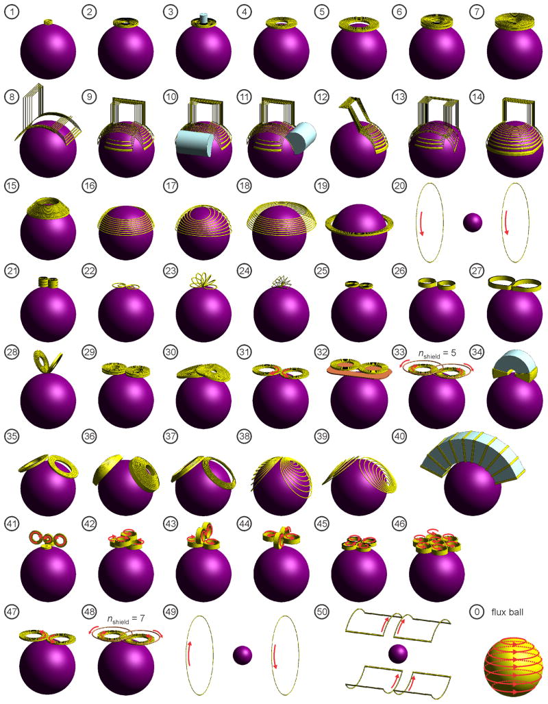
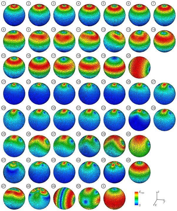
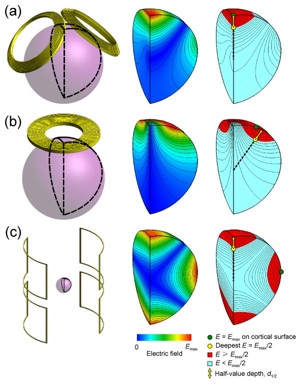
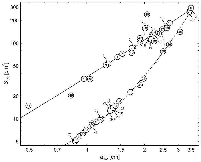
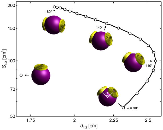
Methods: The electric field distributions induced by 50 TMS coils were simulated in a spherical human head model using the finite element method. For each coil design, we quantified the electric field penetration by the half-value depth, d(1/2), and focality by the tangential spread, S(1/2), defined as the half-value volume (V(1/2)) divided by the half-value depth, S(1/2) = V(1/2)/d(1/2).

Results: The 50 TMS coils exhibit a wide range of electric field focality and depth, but all followed a depth-focality tradeoff: coils with larger half-value depth cannot be as focal as more superficial coils. The ranges of achievable d(1/2) are similar between coils producing circular and figure-8 electric field patterns, ranging 1.0-3.5 cm and 0.9-3.4 cm, respectively. However, figure-8 field coils are more focal, having S(1/2) as low as 5 cm(2) compared to 34 cm(2) for circular field coils.

Conclusions: For any coil design, the ability to directly stimulate deeper brain structures is obtained at the expense of inducing wider electrical field spread. Novel coil designs should be benchmarked against comparison coils with consistent metrics such as d(1/2) and S(1/2).


Figures

Figure 1
Figure 1
Simulation models of 50 TMS coil configurations: (1) Animal mini-coil, (2) Magstim 50 mm circular coil (P/N 9999), (3) 50 mm circular coil with iron core, (4) Magstim 70 mm circular coil (P/N 3192), (5) Magstim 90 mm circular coil (P/N 3192), (6) Magstim animal MST coil, (7) Magstim human MST coil (S/N MP39), (8) Brainsway H coil, (9) Brainsway H1 coil,,–, (10) H1 coil with frontal iron core, (11) H1 coil with lateral iron core, (12) Brainsway H1L coil, (13) Brainsway H2 coil,,,, (14) Brainsway HADD coil, (15) Magstim cap coil, (16) crown coil, (17) crown coil with back-splayed winding, (18) crown coil with back-spaced winding, (19) supraorbital halo coil,, (20) MRI z-gradient coil in parallel-current (Helmholz) mode, (21) 3-layer double coil, (22) double butterfly,,, (23) circular slinky-7 coil,, (24) rectangular slinky-7 coil,,, (25) Magstim 25 mm figure-8 (P/N 1165),, (26) Cadwell Corticoil, (27) Cadwell B-shaped coil, (28) 50 mm V-coil, (29) MagVenture C-B65 butterfly coil, (30) MagVenture MC-B70 butterfly coil,,, (31) Magstim 70 mm figure-8 coil (P/N 9925, 3190), (32) 70 mm figure-8 with shielding plate, (33) 70 mm figure-8 with active shield (5 turns), (34) Neuronetics iron-core figure-8 coil (CRS 2100),, (35) MagVenture D-B80 butterfly coil,, (36) MagVenture MST twin coil, (37) Magstim double cone coil (P/N 9902), (38) eccentric double cone coil with center-dense windings, (39) eccentric double cone coil with center-sparse windings, (40) stretched C-core coil,, (41) 3-D differential coil, (42) 3-D coil array #1, (43) 3-D coil array #2, (44) 3-D coil array #3, (45) Cadwell cloverleaf coil,, (46) circular coil array,, (47) Magstim 70 mm figure-8 coil in reversed-current mode, (48) 70 mm figure-8 with active shield (7 turns), (49) MRI z-gradient coil opposing-current (Maxwell) mode, and (50) MRI x- (or y-) gradient (Golay) coil. The last configuration, labeled “0”, is the ideal “flux ball” coil whose windings are parallel to the circles of latitude of the spherical model and cover the whole head.
Figure 2
Figure 2
Induced electric field distribution on the brain surface by the 50 TMS coils from Figure 1. The electric field magnitude is plotted with a color map normalized to the field maximum in the brain, Emax, for each coil. The arrows indicate the electric field direction.
Figure 3
Figure 3
Examples of electric field characterization for (a) double-cone (#37), (b) 90-mm circular (#5), and (c) MRI x- (or y-) gradient (#50) coils. The left column shows the respective coil and the spherical model representation of the brain. The middle column shows the electric field strength contour and color maps on the quarter-sphere segment of the brain outlined in black on the left. The right column shows the location of the maximum induced electric field on the brain surface, Emax (green circle), and the location of the deepest point where the electric field strength is Emax/2 (yellow circle). Note that the deepest point where E =Emax/2 does not necessarily fall on the same radial line as Emax. The yellow arrow represents the half-value depth, d1/2, which is the radial distance from the cortical surface to the deepest point where the electric field strength is half of its maximum value on the cortical surface. The red portions of the quarter-sphere indicate the regions of the brain exposed to electric field as strong as or stronger than Emax/2; the total volume of these regions is V1/2. The half-value spread, S1/2, is defined as S1/2 = V1/2/d1/2.
Figure 4
Figure 4
Electric field focality quantified by the half-value spread, S1/2, as a function of the half-value depth, d1/2, for the TMS coils in Figure 1. The definitions of metrics d1/2 and S1/2 are illustrated in Figure 2. The solid and dashed lines are curves of best fit of the points corresponding to symmetric circular (#1–7, 15, 16, 19, and 20) and figure-8 (#21–26, 28, 29, 31, 32, 34–40) type coils, respectively. Coils #34* and #40* are the air-core counterparts to ferromagnetic-core coils #34 and 40, respectively. For large coil sizes the depth–focality tradeoff trends for both circular and figure-8 type coils converge to the flux ball (coil #0) which corresponds to uniform magnetic field in the head and has S1/2 = 308 cm2 and d1/2 = 3.5 cm. The dotted line is the S1/2d1/2 locus for the MagVenture MST twin coil (#36) for a range of inter-loop opening angles, replicated from Figure 4.
Figure 5
Figure 5
Electric field S1/2d1/2 locus for the MagVenture MST twin coil (#36) for inter-loop opening angles ranging from 90° to 180°. The field characteristics of one of the twin coil windings is also plotted for comparison.

Comment in

References

    1. Fitzgerald PB, Daskalakis ZJ. The effects of repetitive transcranial magnetic stimulation in the treatment of depression. Expert Rev Med Devices. 2011;8:85–95. - PubMed
    1. Fitzgerald PB, Fountain S, Daskalakis ZJ. A comprehensive review of the effects of rTMS on motor cortical excitability and inhibition. Clin Neurophysiol. 2006;117:2584–2596. - PubMed
    1. Deng Z-D, Peterchev AV, Lisanby SH. Coil design considerations for deep-brain transcranial magnetic stimulation (dTMS). Conf Proc IEEE Eng Med Biol Soc; 2008. pp. 5675–5679. - PubMed
    1. Krings T, Buchbinder BR, Butler WE, Chiappa KH, Jiang HJ, Rosen BR, et al. Stereotactic transcranial magnetic stimulation: correlation with direct electrical cortical stimulation. Neurosurgery. 1997;41:1319–1325. - PubMed
    1. Tofts PS. The distribution of induced currents in magnetic stimulation of the nervous system. Phys Med Biol. 1990;35:1119–1128. - PubMed

Publication types