. 2012 Apr;190(4):1197-224.
doi: 10.1534/genetics.111.128710.

Mitotic spindle form and function

Affiliations

Mitotic spindle form and function

Mark Winey et al. Genetics. 2012 Apr.

Abstract

The Saccharomyces cerevisiae mitotic spindle in budding yeast is exemplified by its simplicity and elegance. Microtubules are nucleated from a crystalline array of proteins organized in the nuclear envelope, known as the spindle pole body in yeast (analogous to the centrosome in larger eukaryotes). The spindle has two classes of nuclear microtubules: kinetochore microtubules and interpolar microtubules. One kinetochore microtubule attaches to a single centromere on each chromosome, while approximately four interpolar microtubules emanate from each pole and interdigitate with interpolar microtubules from the opposite spindle to provide stability to the bipolar spindle. On the cytoplasmic face, two to three microtubules extend from the spindle pole toward the cell cortex. Processes requiring microtubule function are limited to spindles in mitosis and to spindle orientation and nuclear positioning in the cytoplasm. Microtubule function is regulated in large part via products of the 6 kinesin gene family and the 1 cytoplasmic dynein gene. A single bipolar kinesin (Cin8, class Kin-5), together with a depolymerase (Kip3, class Kin-8) or minus-end-directed kinesin (Kar3, class Kin-14), can support spindle function and cell viability. The remarkable feature of yeast cells is that they can survive with microtubules and genes for just two motor proteins, thus providing an unparalleled system to dissect microtubule and motor function within the spindle machine.


Figures

Figure 1
Figure 1
Yeast mitotic spindle structure. Sixteen kinetochore microtubules and four interpolar microtubules emanate from each spindle pole in a haploid cell: 40 MTs/1.5 μm spindle. (Left) The yeast mitotic spindle as seen in the electron microscope (EM) using thin sections of high-pressure frozen and freeze-substituted cells (e.g., Winey et al. 1995). The budded cell contains two SPBs (black arrows) that form a bipolar spindle (microtubules are the filaments between the SPBs in the nucleus). The nuclear envelope (white carets) extends through the bud neck, a typical configuration at this point in the cell cycle. (Right) The yeast mitotic spindle as seen in the light microscope using α-tubulin fused to green fluorescent protein (Tub-GFP, shown in Figure as white protein on black background). The outline of the cell is illustrated by the outline in white. The spindle can be seen at the bud neck and extending into the mother (larger) cell. Astral microtubules that emanate from the spindle pole body can be seen penetrating the daughter (budded cell). (Bottom right) A tomographic reconstruction of a spindle from serial thin sections.
Figure 2
Figure 2
The mitotic spindle in yeast (A, left) is formed from spindle pole bodies (A, right) that are composed of five subcomplexes (B). (A, left) Immunofluoresence of a large-budded mitotic yeast cell showing SPBs marked by Spc42-GFP (green), microtubules (red), and DNA (blue) and electron micrograph (A, right) showing trilaminar ultrastructure. Bar, 100 nm. (Eileen O’Toole, University of Colorado, Boulder). (B) Schematic of the five major functional centrosome subcomplexes. This figure is from Keck et al. (2011) and is reprinted with permission.
Figure 3
Figure 3
A model of the SPB central-plaque structure in cross section (left) and en face (right) based on FRET mapping of interactions and incorporating various structural data about the components in this substructure of the SPB. This figure is from Muller et al. (2005) and is reprinted with permission.
Figure 4
Figure 4
The γ-tubulin complex (Tub4 γ-tubulin, Spc97, and Spc98 as indicated) structure in complex with the N terminus of Spc110 based on cryo-EM from Kollman et al. (2010). A micrograph (A) of the complex in its 13-fold polymeric form. Various views (C–E) of the γ-tubulin complex with the N terminus of Spc110 in the context of the higher-order structure. Various views (F) of a single γ-tubulin complex with the N terminus of Spc110. Note: Panel B from the original figure was not included in the figure reproduction because the panel was not relevant to this article. Reprinted by permission from Macmillan Publishers Ltd: Nature. Kollman et al., copyright 2010.
Figure 5
Figure 5
Domain structure and hierarchy of microtubule plus-end-tracking proteins Bim1 (EB1), Bik1 (CLIP-170), Nip100 (p150glued), Stu1 (CLASP), and Stu2 (XMAP215). (Top left) Bim1 (EB1 family) is delineated by an N-terminal calponin homology domain (CH), an EB1 domain that confers dimerization and a C-terminal EEY motif that binds CAP-Gly domains. Bik1, of the CLIP-170 family, contains an N-terminal CAP-Gly domain, a central coiled-coil (CC) dimerization domain, a C-terminal Zn2+ knuckle domain that can inhibit the ability of CAP-Gly domains to bind tubulin, and a C-terminal ETF motif akin to the EEY motif found in EB1. Nip100 (of the p150glued family) contains a CAP-Gly domain. In the CLASP ortholog, Stu1 contains a microtubule-binding domain (MBD) as well as a kinetochore-binding domain (KtBD). Stu2 contains two N-terminal TOG domains followed by a C-terminal CC dimerization domain. (Top right) Bim1 and Stu2 bind to and regulate plus-end microtubule dynamics (green arrows). SKIP-motif proteins and the CAP-Gly-containing proteins Nip100p150 and Bik1 show a Bim1-dependent microtubule plus-end-tracking activity (blue arrows). Whether Stu1 can plus-end-track autonomously or is Bim1-dependent remains to be elucidated. Regulatory elements are depicted in red. Adapted with permission from K. Slep (2010). (Bottom left) EB1 structure and microtubule binding. Structure of the EB1 N-terminal calponin homology domain (left, orange) reveals seven peripheral helices packed around the central conserved α3 helix. The structures of human EB1 (orange), EB3 (dark gray), and S. cerevisiae Bim1p (light gray) superimposed (bottom) reveal a high degree of structural identity across the EB1 family. The conserved C-terminal EB1 dimerization domain is formed through a coiled coil that folds back at its C-terminal region to form a four-helix bundle. The interface between the coiled coil and the four-helix bundle contains a signature FYF motif involved in SKIP-motif binding. (Bottom middle) Structure and mechanism of the TOG domain-containing Stu2. A cartoon representation of the Drosophila XMAP215 TOG2 domain, delineating the six HEAT Repeats (HR), A–F, forms the elongated domain. Each HEAT repeat is formed by two antiparallel helices bridged by an intra-HEAT loop, positioned here at the top of the domain. (Bottom right) The G59S mutation of human p150glued constructed in yeast. Predicted structures of residues 25–83 for wild-type Nip100 and the Nip100-G45S mutant. The sequence of Nip100 was threaded onto the structure of p150glued. Moore et al. (2009a) have demonstrated that the CAP-Gly domain has a critical role in the initiation and persistence of dynein-dependent movement of the mitotic spindle and nucleus. A single amino acid change, G59S, in the conserved cytoskeletal-associated protein glycine-rich (CAP-Gly) domain of the p150 (glued) subunit of dynactin can cause motor neuron degeneration in humans and mice, which resembles ALS.
Figure 6
Figure 6
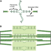
DNA springs in the spindle: model of the organization of cohesin and pericentric chromatin in metaphase (A) DNA of each sister chromatid is held together via intramolecular bridges that extend ∼11.5 kb on either side of the centromere. A transition from intra- to intermolecular linkages results in a cruciform structure. (B) Five (of 16) bioriented sister chromatids are shown with two (of eight) interpolar microtubules. We have proposed that the transition between intramolecular looping and intermolecular cohesion is mobile and, on average, 11.5 kb from the centromere core. DNA adjacent to the centromere may extend to its form length in vivo (depicted as thin orange lines), thereby linking the centromere at kinetochore–microtubule plus ends to strands of intramolecularly paired pericentric chromatin and cohesin that are displaced radially from spindle microtubules. Microtubules and spindle pole bodies are represented by green and black rods, respectively. The 125-bp centromere is wrapped around the Cse4-containing histone in yellow. Nucleosomal chromatin is depicted as green histone cores wrapped around DNA in thin red line. Cohesin is depicted as black ovals linking two strands of nucleosomal DNA. The fluorescence distribution of cohesin is depicted in transparent green. Pericentric chromatin from each of the 16 chromosomes is displaced 70–90 nm radially from the central spindle microtubules. The entire spindle is composed of 32 kinetochore microtubules and eight pole–pole microtubules. From Yeh et al. (2008).
Figure 7
Figure 7
The SPB duplication pathway. The various steps and the genes required at each step of the pathway are indicated (see Spindle pole duplication and separation). Those in blue encode SPB components, those in red encode protein kinases that regulate SPB duplication, and those in purple are other regulators. In brief, the first step is elongation of the half-bridge and the formation of the satellite. The second step is the expansion of the satellite into the duplication plaque and the beginning of the fenestra in the nuclear envelope. The third step is the insertion of the new SPB into the nuclear envelope and the maturation of its nuclear face, creating duplicated side-by-side SPBs. The point of arrest of the duplication pathway by mating factor, in preparation for cellular fusion and karyogamy, is indicated.
Figure 8
Figure 8
Breck Byer’s classic drawing of the yeast cell cycle indicating the state of the SPBs (Byers and Goetsch 1975) to which are added representative models of SPBs and microtubules from electron microscopy and electron tomography studies (Winey et al. 1995; O’Toole et al. 1999). A single SPB in G1 phase (A) has nuclear and cytoplasmic microtubules. A duplicating SPB (B, blue) has a satellite or early duplication plaque (green) on the half-bridge (yellow). (C) Duplicated side-by-side SPBs. Each SPB has nuclear microtubules, and there are a few cytoplasmic microtubules. A short bipolar spindle (D, ∼600 nm) is not well organized. A medial length, likely metaphase, spindle (E, ∼1.5 um) is clearly organized with shorter kinetochore microtubules and the fewer longer microtubules that will form the central spindle. A late-anaphase spindle (F, ∼8 um) and a SPB in such a spindle (enlarged) as seen by electron tomography. The predominant feature of the anaphase spindle are the few tightly packed and twisted microtubules that interdigitate at the spindle midzone. However, the SPB has numerous (nearly 16) very short (30–50 nm) microtubules that are presumably still attached to kinetochores.
Figure 9
Figure 9
Proposed spatial gradient in net kMT plus-end assembly mediates kinetochore congression in yeast. Kinetochores (cyan) congress to attractor zones (yellow arrows) on either side of the spindle equator (dashed-and-dotted line) during yeast metaphase via the plus-end assembly dynamics of kMTs (black). The kMT plus-end assembly dynamics are spatially regulated such that plus-end assembly is favored near the poles (gray) when kMTs are relatively short (favorable assembly zone shown as green gradient) and suppressed near the spindle equator (dashed line) when kMTs are relatively long (assembly suppression zone shown as red gradient). Adapted from Gardner et al. (2008c)
Figure 10
Figure 10
Balance of dynamic pushing and pulling forces in S. cerevisiae.To properly position the pre-anaphase spindle at the bud neck without moving the spindle into the bud, S. cerevisiae provides a balance of pushing and pulling forces (arrows). (A) Growing and shortening microtubules in the mother cell facilitate searching of the cytoplasmic space and establish pushing forces against the cortex to orient the spindle to the bud neck. (B) Stable attachment at the neck could provide a stabilizing force to limit pulling forces from the bud; it could also provide a loading site for actin-based transport of microtubules and dynein-dependent sliding, and/or it could maintain proper positioning at the bud neck. (C) Minus-end-directed movement of cortically anchored dynein provides a strong pulling force to bring the spindle to the bud neck. Dynein is off-loaded to cortical anchors (Num1) where the minus-end activity is stimulated to result in a pulling force that brings the nucleus into the bud (Lee et al. 2005; Markus and Lee 2011). (D) In a redundant pathway, microtubule plus ends are linked through Bim1 and Kar9 to class-V myosin (Myo2) that is moving along polarized actin arrays, facilitating plus-end transport to the bud site. In addition, transport might generate pulling forces to pull the spindle to the bud neck. (E) Finally, end-on attachment at the bud tip where formin nucleates actin growth may also generate force by maintaining attachment to both growing and shortening microtubule plus ends. Adapted from Pearson and Bloom (2004).

References

    1. Abruzzi K. C., Smith A., Chen W., Solomon F., 2002. Protection from free beta-tubulin by the beta-tubulin binding protein Rbl2p. Mol. Cell. Biol. 22: 138–147 - PMC - PubMed
    1. Adams I. R., Kilmartin J. V., 1999. Localization of core spindle pole body (SPB) components during SPB duplication in Saccharomyces cerevisiae. J. Cell Biol. 145: 809–823 - PMC - PubMed
    1. Akhmanova A., Hoogenraad C. C., 2005. Microtubule plus-end-tracking proteins: mechanisms and functions. Curr. Opin. Cell Biol. 17: 47–54 - PubMed
    1. Ali M. Y., Lu H., Bookwalter C. S., Warshaw D. M., Trybus K. M., 2008. Myosin V and kinesin act as tethers to enhance each other’s processivity. Proc. Natl. Acad. Sci. USA 105: 4691–4696 - PMC - PubMed
    1. Allingham J. S., Sproul L. R., Rayment I., Gilbert S. P., 2007. Vik1 modulates microtubule-Kar3 interactions through a motor domain that lacks an active site. Cell 128: 1161–1172 - PMC - PubMed

Publication types

MeSH terms

Substances