

Structure and size determination of bacteriophage P2 and P4 procapsids: function of size responsiveness mutations
- PMID: 22508104
- PMCID: PMC3361666
- DOI: 10.1016/j.jsb.2012.04.002
Structure and size determination of bacteriophage P2 and P4 procapsids: function of size responsiveness mutations
Abstract
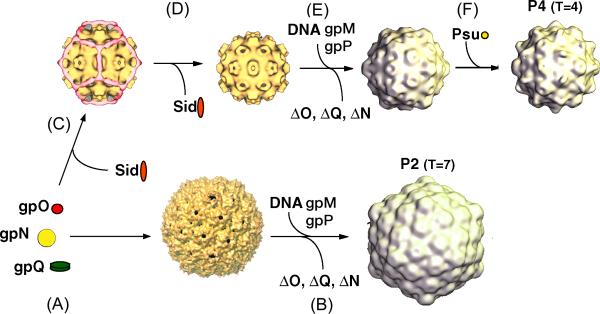
Bacteriophage P4 is dependent on structural proteins supplied by a helper phage, P2, to assemble infectious virions. Bacteriophage P2 normally forms an icosahedral capsid with T=7 symmetry from the gpN capsid protein, the gpO scaffolding protein and the gpQ portal protein. In the presence of P4, however, the same structural proteins are assembled into a smaller capsid with T=4 symmetry. This size determination is effected by the P4-encoded protein Sid, which forms an external scaffold around the small P4 procapsids. Size responsiveness (sir) mutants in gpN fail to assemble small capsids even in the presence of Sid. We have produced large and small procapsids by co-expression of gpN with gpO and Sid, respectively, and applied cryo-electron microscopy and three-dimensional reconstruction methods to visualize these procapsids. gpN has an HK97-like fold and interacts with Sid in an exposed loop where the sir mutations are clustered. The T=7 lattice of P2 has dextro handedness, unlike the laevo lattices of other phages with this fold observed so far.
Copyright © 2012 Elsevier Inc. All rights reserved.
Figures


Similar articles
-
Incorporation of scaffolding protein gpO in bacteriophages P2 and P4.Virology. 2008 Jan 20;370(2):352-61. doi: 10.1016/j.virol.2007.08.039. Epub 2007 Nov 1. Virology. 2008. PMID: 17931675 Free PMC article.
-
Assembly of bacteriophage P2 and P4 procapsids with internal scaffolding protein.Virology. 2006 Apr 25;348(1):133-40. doi: 10.1016/j.virol.2005.12.021. Epub 2006 Feb 7. Virology. 2006. PMID: 16457867
-
Structure of the Capsid Size-Determining Scaffold of "Satellite" Bacteriophage P4.Viruses. 2020 Aug 27;12(9):953. doi: 10.3390/v12090953. Viruses. 2020. PMID: 32867300 Free PMC article.
-
The structure of P4 procapsids produced by coexpression of capsid and external scaffolding proteins.Virology. 2002 Jul 5;298(2):224-31. doi: 10.1006/viro.2002.1485. Virology. 2002. PMID: 12127785
-
Mechanisms of genome propagation and helper exploitation by satellite phage P4.Microbiol Rev. 1993 Sep;57(3):683-702. doi: 10.1128/mr.57.3.683-702.1993. Microbiol Rev. 1993. PMID: 8246844 Free PMC article. Review.
Cited by
-
Capsid expansion of bacteriophage T5 revealed by high resolution cryoelectron microscopy.Proc Natl Acad Sci U S A. 2019 Oct 15;116(42):21037-21046. doi: 10.1073/pnas.1909645116. Epub 2019 Oct 2. Proc Natl Acad Sci U S A. 2019. PMID: 31578255 Free PMC article.
-
The adaptation of temperate bacteriophages to their host genomes.Mol Biol Evol. 2013 Apr;30(4):737-51. doi: 10.1093/molbev/mss279. Epub 2012 Dec 12. Mol Biol Evol. 2013. PMID: 23243039 Free PMC article.
-
Convergent evolution of pathogenicity islands in helper cos phage interference.Philos Trans R Soc Lond B Biol Sci. 2016 Nov 5;371(1707):20150505. doi: 10.1098/rstb.2015.0505. Philos Trans R Soc Lond B Biol Sci. 2016. PMID: 27672154 Free PMC article.
-
Insights into head-tailed viruses infecting extremely halophilic archaea.J Virol. 2013 Mar;87(6):3248-60. doi: 10.1128/JVI.03397-12. Epub 2013 Jan 2. J Virol. 2013. PMID: 23283946 Free PMC article.
-
Transient contacts on the exterior of the HK97 procapsid that are essential for capsid assembly.J Mol Biol. 2014 May 15;426(10):2112-29. doi: 10.1016/j.jmb.2014.03.009. Epub 2014 Mar 20. J Mol Biol. 2014. PMID: 24657766 Free PMC article.
References
-
- Agirrezabala X, Velasquez-Muriel JA, Gomez-Puertas P, Scheres SHW, Carazo JM, Carrascosa JL. Quasi-atomic model of bacteriophage T7 procapsid shell: insights into the structure and evolution of a basic fold. Structure. 2007;15:461–472. - PubMed
-
- Akita F, Chong KT, Tanaka H, Yamashita Y, Miyazaki N, Nakaishi Y, Suzuki M, Namba K, Ono Y, Tsukihara T, Nakagawa A. The crystal structure of a virus-like particle from the hyperthermophilic archaeon Pyrococcus furiosus provides insight into the evolution of viruses. J. Mol. Biol. 2007;368:1469–1483. - PubMed
-
- Bamford DH, Grimes JM, Stuart DI. What does structure tell us about virus evolution? Curr. Opin. Struct. Biol. 2005;15:655–663. - PubMed
Publication types
MeSH terms
Grants and funding
LinkOut - more resources
Full Text Sources
