. 2012 Jun 29;31(13):3020-8.
doi: 10.1038/emboj.2012.118. Epub 2012 May 11.

3'-processing and strand transfer catalysed by retroviral integrase in crystallo

Affiliations

3'-processing and strand transfer catalysed by retroviral integrase in crystallo

Stephen Hare et al. EMBO J. .

Abstract

Retroviral integrase (IN) is responsible for two consecutive reactions, which lead to insertion of a viral DNA copy into a host cell chromosome. Initially, the enzyme removes di- or trinucleotides from viral DNA ends to expose 3'-hydroxyls attached to the invariant CA dinucleotides (3'-processing reaction). Second, it inserts the processed 3'-viral DNA ends into host chromosomal DNA (strand transfer). Herein, we report a crystal structure of prototype foamy virus IN bound to viral DNA prior to 3'-processing. Furthermore, taking advantage of its dependence on divalent metal ion cofactors, we were able to freeze trap the viral enzyme in its ground states containing all the components necessary for 3'-processing or strand transfer. Our results shed light on the mechanics of retroviral DNA integration and explain why HIV IN strand transfer inhibitors are ineffective against the 3'-processing step of integration. The ground state structures moreover highlight a striking substrate mimicry utilized by the inhibitors in their binding to the IN active site and suggest ways to improve upon this clinically relevant class of small molecules.


Conflict of interest statement

The authors declare that they have no conflict of interest.

Figures

Figure 1
Figure 1
Retroviral integration intermediates and detection of 3′-processing and strand transfer in crystallo. (A) Schematic of IN–DNA complexes observed in in vitro systems; a tetramer of IN (cyan oval) assembles on viral DNA ends, forming the intasome; this initial intasomal complex is referred to as the UI. In the presence of Mg2+ or Mn2+ cations, IN catalyses 3′-processing, resulting in the CI. The CI binds target DNA to form the target capture complex (TCC). The STC represents the final post-catalytic state. The reactive and nonreactive DNA strands at each viral DNA end and target DNA are shown as gold, orange and purple lines, respectively; arrowheads represent 3′-ends. Strand transfer inhibitors bind to the CI active sites and prevent formation of the TCC. Letter codes indicate DNA species observed in crystals: N, 19-mer nonreactive viral DNA strand; r and R, 19-mer unprocessed and 17-mer processed reactive strand, respectively; T, self-complementary 30-mer target DNA strands; R+T and t, 34-mer and 13-mer strand transfer products, respectively. (B) Denaturing PAGE analysis of DNA species isolated from UI crystals prior to (lane 3) or following soaking in the presence of Mn2+ (lanes 4–9) or Mg2+ (lane 10). Reaction times are indicated above the gel image; based on relative intensities of the R and r bands, the reaction was ∼10, 20 and 50% complete after 20, 45 and 120 min, respectively. 5′-Labelled N:r and N:R duplexes were loaded in lanes 1 and 2, respectively. Sizes of substrate and product oligonucleotides are indicated to the right of gel. The 5′-end of the nonreactive strand was blocked with a non-radioactive phosphate group to improve detection of the reactive strand during labelling, without perturbing the active site (Supplementary Figure S2). (C) DNA species isolated from TCC crystals prior to (lane 7) or following incubation in Mn2+ (lanes 8–13) or Mg2+ (lane 14) for indicated periods of time; based on relative intensities of the T and t bands, the reaction was ∼30, 70, 90% complete after 30, 120 and 300 s, respectively. Lanes 1–6 contained t, S, T, N, R and annealed N:R DNA samples, respectively. Note that although intasome does not bind target DNA in a sequence-specific fashion, only the symmetric complex crystallizes under the conditions employed (Maertens et al, 2010).
Figure 2
Figure 2
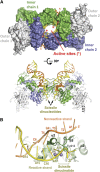
Overall architecture of the retroviral intasome prior to 3′-processing. (A) The UIMn structure viewed in two orientations with IN chains shown in a space-fill mode (top) or as cartoons (bottom); the inner subunits are coloured dark cyan and green and outer chains grey. The reactive and nonreactive viral DNA strands are depicted as yellow and orange cartoons, respectively. Locations of the active sites (asterisks) and the scissile dinucleotides are indicated. Note that the crystallized construct is symmetrized by the presence of two identical viral DNA termini derived from the U5 viral DNA end. The native retroviral nucleoprotein complexes are less symmetric due to the sequence differences of the left (U3) and right (U5) viral DNA termini. In the native PFV UI, only the U5 DNA end is expected to have a scissile dinucleotide, while the U3 end, naturally terminating on a CA sequence, does not undergo 3′-processing (Juretzek et al, 2004). (B) Fraying of the viral DNA end prior to 3′-processing. IN is shown as cartoons (green) with secondary structure elements indicated; selected side chains are shown in sticks. The reactive and nonreactive viral DNA strands are shown as yellow and orange cartoons, respectively, with six terminal nucleotides indicated; grey spheres are Mn atoms.
Figure 3
Figure 3
The IN active site engaged with the non-processed 3′-viral DNA end. (A) Stereo view (wall-eye) on the 3′-end of viral DNA in UIApo. The protein is shown as a semitransparent blue surface and the DNA as a stick representation with the scissile phosphodiester in grey. Hydrogen bonds between the internal phosphodiester of the scissile dinucleotide and protein backbone amides are shown as dashes. (B) Stereo view of the active site bound to non-processed 3′-end of viral DNA end with and without Mn2+. Carbon atoms belonging to the UIApo structure are coloured blue, and those belonging to UIMn are green, while other atoms follow standard coloration: blue for nitrogen, red for oxygen and orange for phosphorus. Spheres represent the manganese ions; black arrow indicates the relocation of the scissile phosphodiester upon metal binding. (C) Stereo view of the active site in the UIMn structure. Metal ions are shown in purple and associated water molecules in red. The large red sphere indicates the water molecule poised to act as a nucleophile in 3′-processing, with potential path indicated with a red dash. (D) The inter metal distances in the different structures, with metals shown as purple spheres, carbons of protein in green, viral DNA in yellow and target DNA in magenta.
Figure 4
Figure 4
Target DNA binding and the strand transfer reaction. (A) Stereo view of target DNA (magenta and purple) overlaid with the position of reactive viral DNA strand before processing (yellow) in TCCMn and UIMn, respectively. The targeted, the upstream and downstream phosphodiesters of the target DNA are labelled in black with ‘0’, ‘−1’ and ‘+1’, respectively; the bases of the reactive viral DNA strand labelled in gold. (B) Relocation of the viral–target DNA phosphodiester bond following strand transfer (black arrow).
Figure 5
Figure 5
Substrate mimicry by the HIV IN strand transfer inhibitors. Active sites of inhibitor-bound CI structures (PDB codes 3OYA, 3OYB, 3OYH, 3OYG, 3S3M) were superposed onto the UIMn (top) or TCCMn (bottom) based on Cα atoms of the active site residues. In the stereo views, raltegravir (3OYA) is shown as sticks with carbon atoms coloured green and fluorine in grey; only the metal chelating oxygen atoms of all other strand transfer inhibitors are shown (brown spheres). Protein is shown as semitransparent cartoons; viral and target DNA and selected IN residues as semitransparent sticks. Metal ions from the UIMn and TCCMn structures are shown as grey and those from the inhibitor-bound structures as green spheres. The pro-S p and the bridging 3′-oxygen atoms of the scissile or target phosphodiester (sticks), water (WNuc) and 3′-hydroxyl nucleophiles are shown as red spheres. The images to the right are related to the stereo views by a 90° rotation, as indicated. Hydrogen bonds discussed in the text are shown as dashed lines. The direction of the nucleophilic attack during 3′-processing or strand transfer is indicated with a pink dashed line. The chemical structure of raltegravir is shown in Supplementary Figure S4.

References

    1. Andrake MD, Ramcharan J, Merkel G, Zhao XZ, Burke TR Jr., Skalka AM (2009) Comparison of metal-dependent catalysis by HIV-1 and ASV integrase proteins using a new and rapid, moderate throughput assay for joining activity in solution. AIDS Res Ther 6: 14. - PMC - PubMed
    1. Brautigam CA, Steitz TA (1998) Structural principles for the inhibition of the 3′–5′ exonuclease activity of Escherichia coli DNA polymerase I by phosphorothioates. J Mol Biol 277: 363–377 - PubMed
    1. Bushman FD, Craigie R (1991) Activities of human immunodeficiency virus (HIV) integration protein in vitro: specific cleavage and integration of HIV DNA. Proc Natl Acad Sci USA 88: 1339–1343 - PMC - PubMed
    1. Cherepanov P, Maertens GN, Hare S (2011) Structural insights into the retroviral DNA integration apparatus. Curr Opin Struct Biol 21: 249–256 - PubMed
    1. Craigie R (2002) Retroviral DNA Integration. InMobile DNA II Craig NL, Craigie R, Gellert M, Lambowitz AM (eds), pp613–630. Washington DC: ASM Press

Publication types