. 2012 Oct;31(10):1837-48.
doi: 10.1109/TMI.2012.2199763. Epub 2012 May 16.

Model-based tomographic reconstruction of objects containing known components

Affiliations

Model-based tomographic reconstruction of objects containing known components

J Webster Stayman et al. IEEE Trans Med Imaging. 2012 Oct.

Abstract

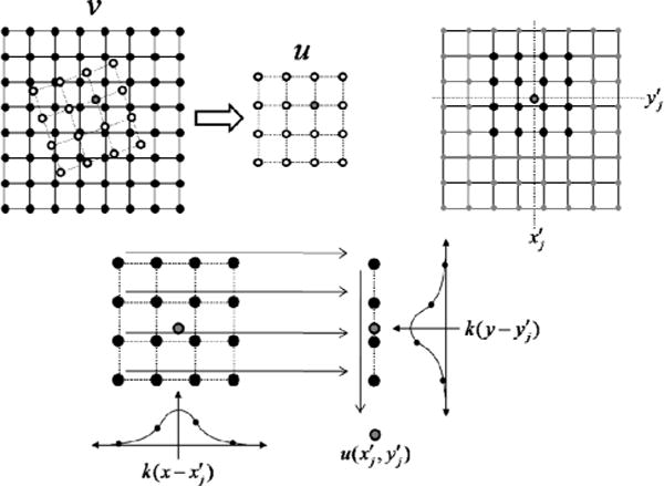
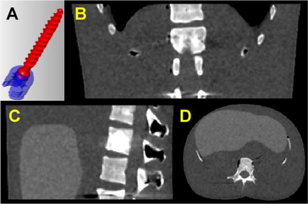
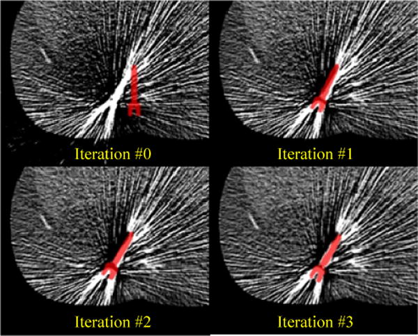
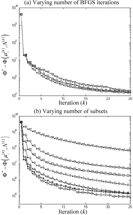
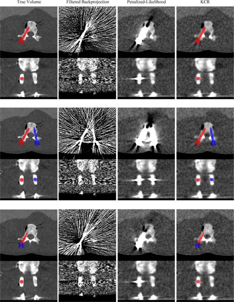
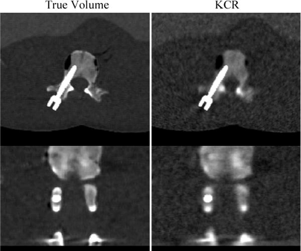
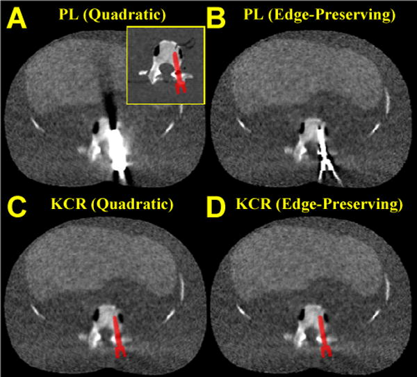
The likelihood of finding manufactured components (surgical tools, implants, etc.) within a tomographic field-of-view has been steadily increasing. One reason is the aging population and proliferation of prosthetic devices, such that more people undergoing diagnostic imaging have existing implants, particularly hip and knee implants. Another reason is that use of intraoperative imaging (e.g., cone-beam CT) for surgical guidance is increasing, wherein surgical tools and devices such as screws and plates are placed within or near to the target anatomy. When these components contain metal, the reconstructed volumes are likely to contain severe artifacts that adversely affect the image quality in tissues both near and far from the component. Because physical models of such components exist, there is a unique opportunity to integrate this knowledge into the reconstruction algorithm to reduce these artifacts. We present a model-based penalized-likelihood estimation approach that explicitly incorporates known information about component geometry and composition. The approach uses an alternating maximization method that jointly estimates the anatomy and the position and pose of each of the known components. We demonstrate that the proposed method can produce nearly artifact-free images even near the boundary of a metal implant in simulated vertebral pedicle screw reconstructions and even under conditions of substantial photon starvation. The simultaneous estimation of device pose also provides quantitative information on device placement that could be valuable to quality assurance and verification of treatment delivery.


Figures

Figure 1
Figure 1
Illustration of kernel-based interpolation in two dimensions. (Upper Left) Mapping of the moving image (v) to the transformed image (u). (Upper Right) A single transformed image point is computed based on a neighborhood of values in the moving image. (Lower) Kernels that are a function of the position in the transformed image are applied in succession along each dimension to yield the value in the transformed image at that point.
Figure 2
Figure 2
(a) CAD model of a pedicle screw. Two components of the polyaxial model are illustrated in red and blue. (b–d) Axial, sagittal, and coronal slices of the digital phantom used as a true representation of the anatomical background.
Figure 3
Figure 3
A sequence of KCR estimated axial slices and implant poses from initial guess to iterations one through three. The pose estimate of the pedicle screw is represented by the red image overlay on the estimated background volume. Iteration zero represents initialization by an FBP reconstruction for the image background and arbitrary placement of the pedicle screw component model in proximity to the true location. Note the simultaneous nature of the estimation process with both registration updates and image updates between successive iterations.
Figure 4
Figure 4
(a) Convergence plots for KCR using alternating applications of image updates using 60 subsets and registration updates using 4 (∇), 6 (○), and 10 (□), BFGS iterations. (b) Convergence plots for alternating updates of 10 BFGS iterations and ordered subsets based image updates using 1 (∇), 5 (○), 10 (□), 20 (◊), 40 (Δ), and 60 (☆) subsets, as well as an approach that uses a dynamic number of subsets (▷). Objective function differences are plotted after both the registration block (identifying symbol) and after the image update (◎).
Figure 5
Figure 5
Illustration of the image quality of KCR compared to FBP and traditional PL estimation. Axial and coronal images are presented for each method and each pedicle screw implant scenario: Top) Unilateral single-component screw; Middle) Bilateral single-component screws; Bottom) Unilateral two-component polyaxial screw. The window and level for all images is 500 and 150 HU, respectively. The color overlay in the true image (left) shows the true pose of the component(s), whereas that in the KCR reconstruction (right) shows the pose as estimated by the simultaneous registration and reconstruction process.
Figure 6
Figure 6
Illustration of the total attenuation (μ) for the single component unilateral screw case: (Left) True phantom, (Right) KCR. Since KCR estimates both the background attenuation (μ*) and the registration parameters, Λ, one may represent the result as either a traditional attenuation image (Figure 6 (right)) or with color overlay (Figure 5 (right)) – whichever better suits display preferences and dynamic range. The window and level for all images is 800 and 300 HU, respectively.
Figure 7
Figure 7
The effect of varying the regularization parameter in KCR. While there is a clear noise-resolution trade-off (viz., larger β decreasing the noise and sacrificing spatial resolution), all of the images are largely free of streak artifacts. The window and level for all images is 500 and 150 HU, respectively.
Figure 8
Figure 8
A comparison of quadratic versus edge-preserving penalties for both penalized-likelihood and KCR approaches. Reconstructions of a single pedicle screw implant (truth image near the implant shown in the yellow inset) are shown for A) PL with quadratic penalty, B) PL with edge-preserving penalty, C) KCR with quadratic penalty, and D) KCR with edge-preserving penalty. The regularization parameters for PL and KCR are matched for each choice of penalty, but the edge-preserving penalty has been optimized for PL image quality. While the edge-preserving penalty may be tuned to mitigate artifacts associated with the implant in the PL reconstruction, KCR can provide nearly artifact-free reconstructions across a range of parameter choices.

References

    1. De Man B, et al. Metal streak artifacts in X-ray computed tomography: A simulation study. IEEE Trans Nuclear Science. 1999;46:691–696.
    1. Barrett JF, Keat N. Artifacts in CT: recognition and avoidance. Radiographics. 2004 Nov-Dec;24:1679–91. - PubMed
    1. Stulberg SD, et al. Monitoring pelvic osteolysis following total hip replacement surgery: an algorithm for surveillance. J Bone Joint Surg Am. 2002;84-A(Suppl 2):116–22. - PubMed
    1. Holly LT, Foley KT. Three-dimensional fluoroscopy-guided percutaneous thoracolumbar pedicle screw placement. Technical note. J Neurosurg. 2003 Oct;99:324–9. - PubMed
    1. Wang MY, et al. Reliability of three-dimensional fluoroscopy for detecting pedicle screw violations in the thoracic and lumbar spine. Neurosurgery. 2004 May;54:1138–42. discussion 1142–3. - PubMed

Publication types