. 2012;7(6):e38011.
doi: 10.1371/journal.pone.0038011. Epub 2012 Jun 19.

TrakEM2 software for neural circuit reconstruction

Affiliations

TrakEM2 software for neural circuit reconstruction

Albert Cardona et al. PLoS One. 2012.

Abstract

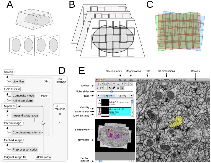
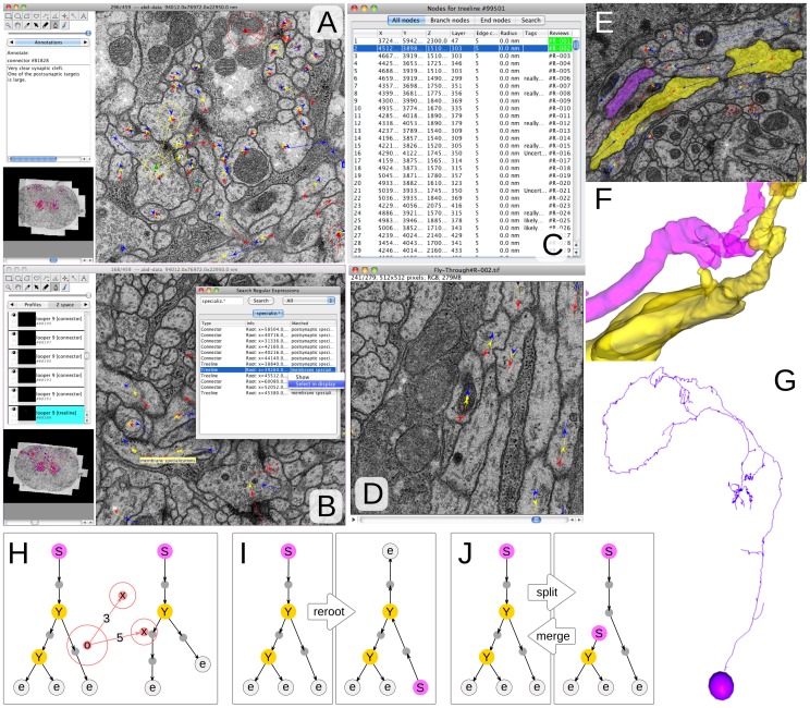
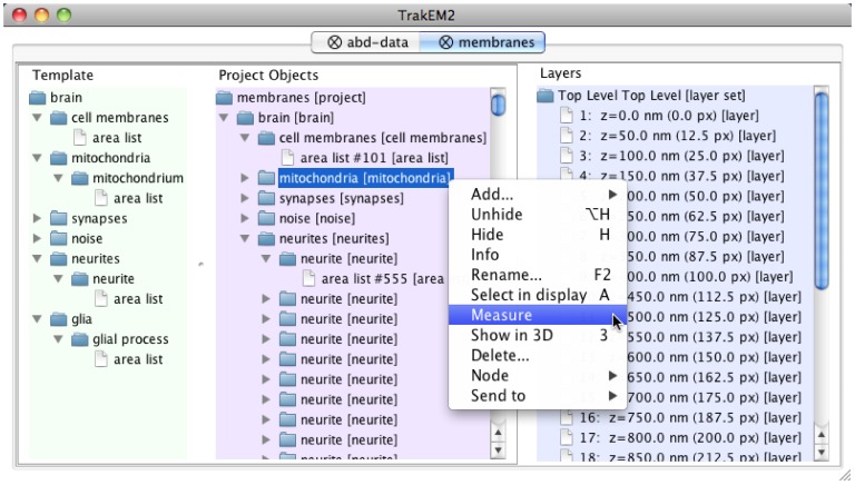
A key challenge in neuroscience is the expeditious reconstruction of neuronal circuits. For model systems such as Drosophila and C. elegans, the limiting step is no longer the acquisition of imagery but the extraction of the circuit from images. For this purpose, we designed a software application, TrakEM2, that addresses the systematic reconstruction of neuronal circuits from large electron microscopical and optical image volumes. We address the challenges of image volume composition from individual, deformed images; of the reconstruction of neuronal arbors and annotation of synapses with fast manual and semi-automatic methods; and the management of large collections of both images and annotations. The output is a neural circuit of 3d arbors and synapses, encoded in NeuroML and other formats, ready for analysis.


Conflict of interest statement

Competing Interests: The authors have declared that no competing interests exist.

Figures

Figure 1
Figure 1. From a resin block to serial 2d image montages.
A Serial EM is performed on a block of tissue embedded in hardened plastic resin. B Sections are imaged with multiple overlapping image tiles. C The imprecision in the positioning of the camera and the numerous non-linear deformations demand of an automatic multi-section image registration procedure that computes the best possible transformation for each tile without introducing gross deformations. D TrakEM2 operates only on original images, which are treated as read-only. A preprocessor script specified invidually for every image alters the image after loading from disk and before the rest of TrakEM2 has access to it, enabling changes of scale, of look-up table, data type, and any pixel-level operation. A Patch object encapsulates the image file path and a set of properties such as the alpha mask, the coordinate transforms (linear and non-linear image transformations) and the desired image display range and composite mode, among others. The precomputed mipmaps store most of the Patch information in compressed 8-bit files ready for display. The image for the field of view is constructed from composing multiple Patch instances according to their location and composite rules (overlay, subtract, add, multiply, difference and Colorize YCbCr), and is then filtered, if desired, for dynamic interactive image enhancement. E The TrakEM2 Display presents the field of view showing a single section and the images, segmentations and annotations present in that section. The Display provides access to tools for manipulating and analyzing all imported images and reconstructed elements.
Figure 2
Figure 2. Neural circuit reconstruction with skeletonized neural arbors and connectors to relate them at synaptic sites.
A Snapshot illustrating the use of connectors to relate neural arbors. The connector in green (notice the ‘o’ node with a yellow circle around; it has three targets–it’s a polyadic insect synapse), each of which is represented within the section by a node with an arrow head that falls within the circle of each target. To the left, notice the use of text annotations to describe the synapse. B Search with regular expressions locates any objects of interest, in this case a “membrane specializations” tag in a neuronal arbor. C The tabular view for a neural arbor lists all nodes, branch nodes, end nodes or a subset whose tags match a regular expression. All columns are sortable, and clicking on each row positions the display on the node. The last column titled “Reviews” indicates which cables of the neuron have already been reviewed (in green) to correct for missing branches or synapses or other issues. D A review stack is precomputed for fast visualization of the cable of interest, each section centered on the node. The visual flow through the stack helps in catching reconstruction errors. E “Area trees” are skeleton arbors whose nodes have 2d areas associated. F 3d rendering of two “area trees”, a section of which are depicted in E. G 3d rendering of the nucleus (represented by a “ball”) and the arbor (represented by a “treeline”) of a neuron in the insect brain. H–J Cartons of the skeletons used for reconstruction. The root node is labeled with an “S”, the branch nodes with “Y” and the end nodes with “e”. In H, a “connector” relates the nodes of two arbors, with specific confidence value for the relationship. These confidence values exist on the edges that relate the arbor’s nodes as well (not shown). I Rerooting changes the perspective, but not the topology, of the tree. By convention we position the root node at the soma. J Two common and trivial operations on trees are split and merge.
Figure 3
Figure 3. Hierarchical organization of reconstructed objects.
A Template (to the left) restricts the expression of nested abstract concepts (such as “brain”, “mitochondria”, etc.) and indicates what other abstract types (e.g. a “glia” is represented by one or more “glial process” instances) or primitive types (such as “area list”, “treeline”, “connector”, “ball”, etc) they may be represented with. All elements of the Template are specific of each reconstruction project and user-defined. In the center, Project Objects displays the actual instances of the abstract, templated objects, which encapsulate and organize in many levels of abstract types the primitive segmentation types (e.g. “area list”). The hierarchical structure assigns meaning to what otherwise would be an unordered heap of primitive types. Each instance of a primitive type acquires a unique identifier (such as “#101 [area list]” ). Each group may be measured jointly, or visualized in 3d, shown/hidden, removed, etc., as illustrated in the contextual menu for the selected “mitochondria” group (highlighted in blue). To the right, the Layers list all sections in the project (a “Layer” holds the data for a single tissue section). From this graphical interface, an independent view may be opened for each section.

References

    1. Helmstaedter M, Briggman K, Denk W. 3D structural imaging of the brain with photons and electrons. Curr Opin Neurobiol. 2008;18:633–41. - PubMed
    1. Briggman K, Bock D. Volume electron microscopy for neuronal circuit reconstruction. Curr Opin Neurobiol: [Nov 23 Epub ahead of print] 2011. - PubMed
    1. Denk W, Horstmann H. Serial block–face scanning electron microscopy to reconstruct threedimensional tissue nanostructure. PLoS Biology. 2004;2:e329. - PMC - PubMed
    1. Suloway C, Pulokas J, Fellmann D, Cheng A, Guerra F, et al. Automated molecular microscopy: the new Leginon system. Journal of Structural Biology. 2005;151:41–60. - PubMed
    1. Mastronarde D. Automated electron microscope tomography using robust prediction of specimen movements. J Struct Biol. 2005;152:36–51. - PubMed

Publication types

LinkOut - more resources