. 2012 Jun 26:3:921.
doi: 10.1038/ncomms1914.

Microscopic magnetic stimulation of neural tissue

Affiliations
Free PMC article

Microscopic magnetic stimulation of neural tissue

Giorgio Bonmassar et al. Nat Commun. .
Free PMC article

Abstract

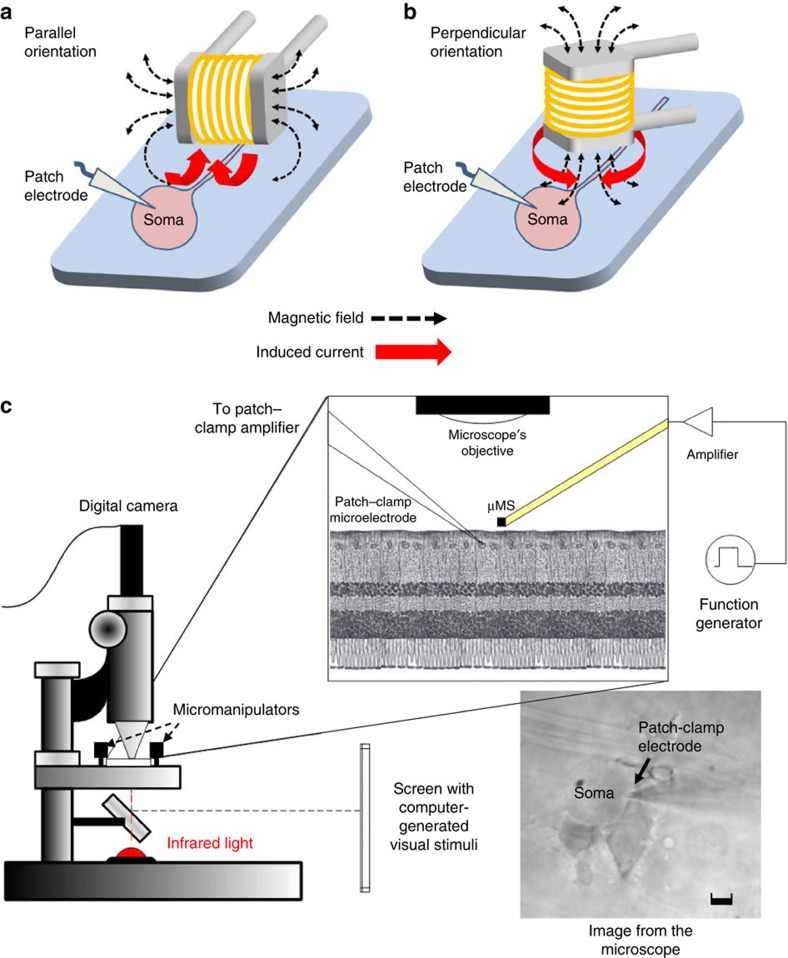
Electrical stimulation is currently used to treat a wide range of cardiovascular, sensory and neurological diseases. Despite its success, there are significant limitations to its application, including incompatibility with magnetic resonance imaging, limited control of electric fields and decreased performance associated with tissue inflammation. Magnetic stimulation overcomes these limitations but existing devices (that is, transcranial magnetic stimulation) are large, reducing their translation to chronic applications. In addition, existing devices are not effective for deeper, sub-cortical targets. Here we demonstrate that sub-millimeter coils can activate neuronal tissue. Interestingly, the results of both modelling and physiological experiments suggest that different spatial orientations of the coils relative to the neuronal tissue can be used to generate specific neural responses. These results raise the possibility that micro-magnetic stimulation coils, small enough to be implanted within the brain parenchyma, may prove to be an effective alternative to existing stimulation devices.


Figures

Figure 1
Figure 1. The FEM simulations.
(a) Three-dimensional distribution of the electric field around the coil starting at 100 μm from the edge of the device. (b) Three-dimensional distribution of the electric field starting at 100 μm below the terminal of the coil. (c) Plot of the radial distribution of the electric field from different elevations. Legend shows the different elevations from coil-center. (d) Plot of the axial distribution of the electric field from different radial distances from the axis of the device. Legend shows the different radial distances from coil-center.
Figure 2
Figure 2. Structure of the inductor.
(a) Image of the inductor used in the electrophysiological experiments. (b) The outer layer of the inductor was chemically dissolved to expose the structure of the underlying solenoid.
Figure 3
Figure 3. Experimental setup of the micro magnetic stimulation of retinal neurons.
(a,b) The two different stimulation-coil orientations that were tested: parallel (a) and perpendicular (b) refer to the relationship between the main axis of the coil and the retinal surface. (c) The retinal preparation was extracted and placed in a small recording chamber with the ganglion cell side facing up. Stimulation was delivered by a small coil located ~300 μm above the ganglion cell and responses were recorded via cell-attached patch–clamp electrodes positioned on the ganglion cell surface. The retina was illuminated via an infrared source and observed via a digital camera (Scale bar, 5 μm). A computer-controlled screen was used to project visual stimuli onto the retina.
Figure 4
Figure 4. μMS coil orientation alters neuronal response.
(a) Ganglion cell responses to a single pulse of μMS (five repetitions); input to the microcoil is shown at top. Responses consisted of a prolonged stimulus artefact followed by a series of biphasic waveforms. (b) Overlay of light-evoked action potential and μMS-evoked biphasic waveform. Each trace is the average of five responses. Horizontal offset of the traces was utilized to facilitate comparison. (c) Peri-stimulus histogram of the firing rate for the five repetitions shown in (a). (Bin width: 10 ms). Stimulus pulse amplitude was 3 V and the main axis of the coil was oriented parallel to and 300 μm from the retinal surface. (d) Ganglion cell responses to a single μMS pulse when the main axis of coil was oriented perpendicular to retinal surface (overlay of five trials). (e) An expanded view of the responses; note three of the five traces elicited action potentials. (f) An expanded view of a single trial for which an action potential was elicited.
Figure 5
Figure 5. Stimulus amplitude and coil-to-cell distance alter response properties.
(a) Microcoil input (top trace) and ganglion cell response (bottom traces) to a series of increasing amplitude pulses (parallel-oriented coil). Amplitude levels range from 4 to 6 V. (b) Summary of responses to increasing amplitude stimulation for parallel orientation. Each point represents the average number of spikes elicited at the corresponding amplitude; lines connect all points from a given cell. (c) Summary of responses from perpendicular orientation. (d,e) The onset latencies of elicited spikes as a function of amplitude for stimulation in the parallel (d) and perpendicular (e) orientation. Bars represent standard errors (n=5). (f,g) Response sensitivity to location of the coil. Number of spikes is plotted as a function of stimulus amplitude for three different separations between coil and retina. At each separation, the number of spikes was averaged across five repetitions. (f) Parallel orientation of coil. (g) Perpendicular orientation of coil.
Figure 6
Figure 6. Magnetic and electric field distributions on the yz-plane.
(a) The magnetic field (in Tesla) distribution on the yz-plane (x=0) μm using the same coordinate system as in Fig. 1. (b) The magnitude of the electric field (V m−1) induced in and around the microcoil. The colourmap shows the current density at each point of the plane, and the lines uniformly sample the magnetic flux density in 20 bins.

References

    1. Wichmann T. & Delong M. R. Deep brain stimulation for neurologic and neuropsychiatric disorders. Neuron 52, 197–204 (2006). - PubMed
    1. Montgomery E. B. Jr & Gale J. T. Mechanisms of action of deep brain stimulation(DBS). Neurosci. Biobehav. Rev. 32, 388–407 (2008). - PubMed
    1. Wilson B. S. & Dorman M. F. Cochlear implants: current designs and future possibilities. J. Rehabil. Res. Dev. 45, 695–730 (2008). - PubMed
    1. Laferrier J. Z. & Gailey R. Advances in lower-limb prosthetic technology. Phys. Med. Rehabil. Clin. N. Am. 21, 87–110 (2010). - PubMed
    1. Loewenstein J. I., Montezuma S. R. & Rizzo J. F. 3rd Outer retinal degeneration: an electronic retinal prosthesis as a treatment strategy. Arch. Ophthalmol. 122, 587–596 (2004). - PubMed

Publication types